
Electronics Fundamentals: Circuits, Devices & Applications
8th Edition
ISBN: 9780135072950
Author: Thomas L. Floyd, David Buchla
Publisher: Prentice Hall
expand_more
expand_more
format_list_bulleted
Concept explainers
Videos
Textbook Question
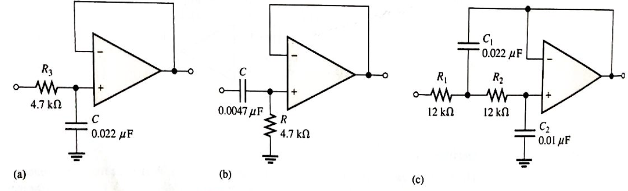
Chapter 19, Problem 19P
Calculate the critical frequencies for the filters in Figure 19-68.
Expert Solution & Answer
Want to see the full answer?
Check out a sample textbook solution
Students have asked these similar questions
The complementary commutation
circuit configuration has 2 SCRS to
work together at the same time
always
O sometimes
O never
When the input signal is AC voltage
source reaches zero at every cycle,
this will turn the thyristor OFF due to
natural behaviour of the source
voltage. This is called
O Natural commutation
O Forced commutation
O Resonant pulse commutation
Usually, a multistage amplifier connection can be used to increase the overall
small-signal voltage gain and to provideoutput impedance.
A very high
B) zero
(c) infinite
D) very low
Question Vv
DRAW the connection diagram for the following circuits so they can be built later
-Band pass filter with minimum Q of 10-AB power amplifier with a load of 4 ohms at 5W with maximum input of 1vpp (use bjt)-7 kHz RC Oscillator
Chapter 19 Solutions
Electronics Fundamentals: Circuits, Devices & Applications
Ch. 19 - A comparator will have a positive output whenever...Ch. 19 - Prob. 2TFQCh. 19 - Prob. 3TFQCh. 19 - Prob. 4TFQCh. 19 - Prob. 5TFQCh. 19 - The output of a Wien-bridge oscillator is a...Ch. 19 - A Wien-bridge oscillator uses both positive and...Ch. 19 - A two-pole filter has a maximum roll-off rate of...Ch. 19 - Prob. 9TFQCh. 19 - Prob. 10TFQ
Ch. 19 - Prob. 1STCh. 19 - To use a comparator for zero-level detection, the...Ch. 19 - Prob. 3STCh. 19 - Prob. 4STCh. 19 - The gain of the amplifier in Question 4 is -1 -2.2...Ch. 19 - To convert a summing amplifier to an averaging...Ch. 19 - Prob. 7STCh. 19 - Prob. 8STCh. 19 - The feedback path in an op-amp differentiator...Ch. 19 - Prob. 10STCh. 19 - Prob. 11STCh. 19 - Prob. 12STCh. 19 - Determine the output level (maximum positive or...Ch. 19 - A certain op-amp has open-loop gain of 80,000. The...Ch. 19 - Prob. 3PCh. 19 - Determine the output voltage for each circuit in...Ch. 19 - Determine the following in Figure 19—62: VR1 and...Ch. 19 - Find the value of Rf necessary to produce an...Ch. 19 - Find the output voltage when the input voltages...Ch. 19 - Determine the values of the input resistors...Ch. 19 - Determine the rate of change of the output voltage...Ch. 19 - A triangular waveform is applied to the input of...Ch. 19 - Prob. 11PCh. 19 - Calculate the resonant frequency of a lead-lag...Ch. 19 - Determine the JFET drain-to-source resistance in...Ch. 19 - Explain the purpose of D1 in Figure 19-66.Ch. 19 - Find the frequency of oscillation for the...Ch. 19 - What type of signal does the circuit in Figure...Ch. 19 - Prob. 17PCh. 19 - Determine the number of poles in each active...Ch. 19 - Calculate the critical frequencies for the filters...Ch. 19 - Determine the bandwidth and center frequency of...Ch. 19 - Determine the output voltage for the series...Ch. 19 - If R3 in figure 19-70 is doubled, what happens to...Ch. 19 - Prob. 23PCh. 19 - A series voltage regulator with constant-current...Ch. 19 - If R4 (determined in Problem 24) is halved, what...Ch. 19 - In the shunt regulator of Figure 19-72, when the...Ch. 19 - Assume that IL remains constant and VIN increases...Ch. 19 - Open file P19-29; files are found at...Ch. 19 - Open file P19-30 and determine if there is a...
Knowledge Booster


Learn more about
Need a deep-dive on the concept behind this application? Look no further. Learn more about this topic, electrical-engineering and related others by exploring similar questions and additional content below.Similar questions
- Part C: Voltage Regulators 1. Determine the output voltage for the series regulator in Figure 17-46. +12 Vo R₁ 10 kn 2.4 V Q₁ o VOUT R₂ 5.6 kn www R₂ 2.2kQarrow_forwardIn non-inverting amplifier, the phase shift between the input and the output is equal toarrow_forwardWhat is the modulation index value if Vmax=5.9v and Vmin=1.2v? O a. 0.425 O b. 0.5 O .0.14 O d. 0.662arrow_forward
- In non-inverting amplifier, the phase shift between the input and the output is equal to 0° 90° 180° None of the abovearrow_forwardA system has 30% overshoot and settling time of 5 sec for unit step input. The resonant peak of the system is A 1.1 B 1.7 C 1.3 D 1.5arrow_forwardIn a certain oscillator, Av=120z200°. The attenuation of the feedback circuit must be 0.0083/160 0.0083z-20 0.0083 0.0098arrow_forward
- deriving of the are Hall Voltage Value ans Ave= #S Sin(wt) dtarrow_forwardQ3/ Determine the centre frequency, maximum gain, bandwidth and type filter for the circuiting figure. 1 k Ohm 0.022 uF 0.047 uF 0.047 uF VI 1 k Ohm 1 k Ohm HE HE Vo HOhm 560 Ohm 1 K 560 Ohm 0.022 uF 1 k Ohm 1 k Ohmarrow_forwardIf the co-channel interference increases , it means that the interchannel interference reduces the bandwidth is reduced the number of reuse frequency increases the cluster size is decreasedarrow_forward
- What type of filter in the circuit fór the figure below TR ER outarrow_forwardFor the cascade connection given below, Find the input voltage Vin to get an output voltage Vout = 19.4 V Vn Vout A, = 4 A, = 15 Vin Varrow_forward19 - S. What is the time constant of the circuit in the figure? O A) RC/16 O B) 8 RC O C) 16 RC O D) RC/8 O E) RCarrow_forward
arrow_back_ios
SEE MORE QUESTIONS
arrow_forward_ios
Recommended textbooks for you
 Introductory Circuit Analysis (13th Edition)Electrical EngineeringISBN:9780133923605Author:Robert L. BoylestadPublisher:PEARSON
 Delmar's Standard Textbook Of ElectricityElectrical EngineeringISBN:9781337900348Author:Stephen L. HermanPublisher:Cengage Learning
 Programmable Logic ControllersElectrical EngineeringISBN:9780073373843Author:Frank D. PetruzellaPublisher:McGraw-Hill Education
 Fundamentals of Electric CircuitsElectrical EngineeringISBN:9780078028229Author:Charles K Alexander, Matthew SadikuPublisher:McGraw-Hill Education
 Electric Circuits. (11th Edition)Electrical EngineeringISBN:9780134746968Author:James W. Nilsson, Susan RiedelPublisher:PEARSON
 Engineering ElectromagneticsElectrical EngineeringISBN:9780078028151Author:Hayt, William H. (william Hart), Jr, BUCK, John A.Publisher:Mcgraw-hill Education,
Introductory Circuit Analysis (13th Edition)
Electrical Engineering
ISBN:9780133923605
Author:Robert L. Boylestad
Publisher:PEARSON
Delmar's Standard Textbook Of Electricity
Electrical Engineering
ISBN:9781337900348
Author:Stephen L. Herman
Publisher:Cengage Learning
Programmable Logic Controllers
Electrical Engineering
ISBN:9780073373843
Author:Frank D. Petruzella
Publisher:McGraw-Hill Education
Fundamentals of Electric Circuits
Electrical Engineering
ISBN:9780078028229
Author:Charles K Alexander, Matthew Sadiku
Publisher:McGraw-Hill Education
Electric Circuits. (11th Edition)
Electrical Engineering
ISBN:9780134746968
Author:James W. Nilsson, Susan Riedel
Publisher:PEARSON
Engineering Electromagnetics
Electrical Engineering
ISBN:9780078028151
Author:Hayt, William H. (william Hart), Jr, BUCK, John A.
Publisher:Mcgraw-hill Education,
Designing a sample & hold-circuit from scratch; Author: Moritz Klein;https://www.youtube.com/watch?v=kIJqzkRe4do;License: Standard Youtube License