Power System Analysis and Design (MindTap Course List)
6th Edition
ISBN: 9781305632134
Author: J. Duncan Glover, Thomas Overbye, Mulukutla S. Sarma
Publisher: Cengage Learning
expand_more
expand_more
format_list_bulleted
Question
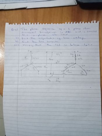
Find;-
magnitude of line voltages
Line currents
Verify that th eload is balanced, i.e In = 0

Transcribed Image Text:Q4)
The phase sequence
connected bustane
sequence of a 3 phose star
3
1)
Find the
phase
magnitudes of
is ABC
ste- loc d
and is connected
une
voltages
(1)
Find
the line
cuments
11
Verify that
the
loc d
2
Selece
IN=
a
+
JA
Can
30
EAN
Eau 3120v 20°
Eng
3 42
F
ECN
e
Egy
Ice
3л
Ven
www
m
sen
41
3
Expert Solution
This question has been solved!
Explore an expertly crafted, step-by-step solution for a thorough understanding of key concepts.
Step by stepSolved in 2 steps with 2 images

Knowledge Booster
Similar questions
- What's 23arrow_forwardConvert the following instantaneous currents to phasors, using cos(t) as the reference. Give your answers in both rectangular and polar form. (a) i(t)=5002cos(t30) (b) i(t)=4sin(t+30) (c) i(t)=5cos(t15)+42sin(t+30)arrow_forward1) Two identical voltage waveforms of difference phase angles are shown in Figure B. Write down the expression of waveforms A and B clearly. HUS Voltage (V) 8 0 K/N B 7: ST otarrow_forward
- Ohmic components have a V-I curve O Non-linear VI curve. Parabolic VI curve. Sinusoidal VI curve. Straight line VI curve.arrow_forwardUsing superposition, determine the current through the inductance XL for each network in the figurearrow_forwardI need to know how I can change the circuit values to make inductive reactance dominant? This wil cause VL and VR to be in phase and VC to be 180 degrees out of phase with them both.arrow_forward
- Determine ZT for the circuit if inductive reactive is 10220 and resistance is 9850. Answer:arrow_forwardQUESTION 3 An inductor, a capacitor, and a resistor are connected in parallel with a function generator. The inductor draws 100mA RMS, the capacitor draws 150mA RMS, and the resistor draws 200mA RMS. Find the magnitude of the total current. O 450mA RMS O 544mA RMS O 352mA RMS O 206mA RMSarrow_forwardAresistor and inductor are connected in parallel to a 120 volt, 60 Hz line. The circuit nas a current flow of 3 amperes. The resistor has a resistance of 72 2. What is the induc- tance of the inductor? gaiau cladi slgns adsarrow_forward
- 0 !!! a *Further Engineering Mathematic X + File | C:/Users/user/Downloads/Further%20Engineering%20MathematicsAssignment-2.pdf Draw T Read aloud CD 9. The two complex numbers V and W represent two reactances connected in series. Calculate the total reactance by finding their sum. AF 3+j4 B = 4-j5 C = 5-j2 D=1-j3 E = 2 +j3FF" FF 4+j1 3 of 4 10. The complex numbers V and W represent two force vectors. Place them on an Argand diagram and calculate the difference between them. 11. Use your given values of V and W to represent the reactances Z₁, Z₂ (as shown in the circuit diagram). Calculate the current flowing in the circuit in polar form if the voltage is v = 1220° and V i = ZTotal Z₁ Z₂ o J (¹) ENG T 60 11:16 PM 3/17/2023 xarrow_forwardThe circuit shown in figure EM1-1 shows an AC voltage source VAC connected in series with a load that has • resistance R=280 Ohms, inductance L=1.1mH, and • capacitance C=4.7mF. Calculate values of, and select the apporpriate answer from the list from the list below for • the frequency, fres (in Hz) of the AC source that results in resonance in the load and the impedance, Zres (in Ohms) of the load at this frequency. ● Resonant Frequency, fres= ✓ Hz Impedance of the Load at Resonance, Zres= R 280 Ω ✓ Ohms V. AC L 4.7 mF 1.1 mH Figure EM1-1 Downloadable imagearrow_forwardPlease disregard the question on the picture. Here's the right question, at what frequency will the value of the impedance be twice that at 25Hz (refer to the given in question #20).arrow_forward
arrow_back_ios
SEE MORE QUESTIONS
arrow_forward_ios
Recommended textbooks for you
 Power System Analysis and Design (MindTap Course ...Electrical EngineeringISBN:9781305632134Author:J. Duncan Glover, Thomas Overbye, Mulukutla S. SarmaPublisher:Cengage Learning

Power System Analysis and Design (MindTap Course ...
Electrical Engineering
ISBN:9781305632134
Author:J. Duncan Glover, Thomas Overbye, Mulukutla S. Sarma
Publisher:Cengage Learning