
Introductory Circuit Analysis (13th Edition)
13th Edition
ISBN: 9780133923605
Author: Robert L. Boylestad
Publisher: PEARSON
expand_more
expand_more
format_list_bulleted
Videos
Textbook Question
Chapter 11, Problem 44P
For the network in Fig. 11.109.
a. Find the mathematical expressions for the voltage vL and the current iL following the closing of the switch.
b. Sketch the waveforms vL and iL obtained in part(a).
c. Determine the mathematical expression for the voltage vL3 following the closing of the switch, and sketch the waveform.
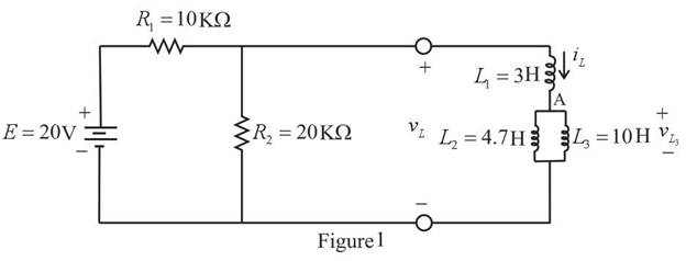
Fig. 11.109
Expert Solution & Answer
Want to see the full answer?
Check out a sample textbook solution
Students have asked these similar questions
8. Liquids with solid impurities
a) Have higher dielectrie strength
b) Of large size have higher dielectric strength
c) Have lower dielectric strength as compared to pure liquids
d) None of the above
9. Peak to peak ripple is defined as
a) the difference between average de voltage and peak value
b) the difference between maximum and minimum de voltage
c) the difference between maximum ac and average dc voltages
d) the difference between ac (rms) and average de voltages
10. In a Cockroft-Walton circuit, input voltage 100 kV load current 25 mA, supply
frequency 100 Hz, each capacitor 10 nF. The optimum no. of stages for maximum
output voltage is
a) 1
b) 2
c) 10
d) 35
Electrical engineering problem
A circuit consists of an AC voltage source, a 10-ohm resistor, and a capacitor, all connected in series. The magnitude of the impedance of the capacitor is also 10 ohms. Which of the following is true about the source voltage and the current through the circuit?
a. Insufficient information is given.
b. The source voltage will lag the current.
c. The source voltage will lead the current.
d. The source voltage will be in-phase with the current.
Chapter 11 Solutions
Introductory Circuit Analysis (13th Edition)
Ch. 11 - For the electromagnet in Fig. 11.75: a. Find the...Ch. 11 - For the inductor in Fig. 11.76, find the...Ch. 11 - a. Repeat Problem 2 with a ferromagnetic core with...Ch. 11 - For the inductor in Fig. 11.77, find the...Ch. 11 - An air-core inductor has a total inductance of 4.7...Ch. 11 - What are the inductance and the range of expected...Ch. 11 - If the flux linking a coil of 50 turns changes at...Ch. 11 - Determine the rate of change of flux linking a...Ch. 11 - How many turns does a coil have if 42 mV are...Ch. 11 - Find the voltage induced across a coil of 22 mH if...
Ch. 11 - For the circuit of Fig. 11.78 composed of standard...Ch. 11 - For the circuit in Fig. 11.79 composed of standard...Ch. 11 - For the network of Fig. 11.80. a. Write the...Ch. 11 - Give a supply of 18 V, use standard values to...Ch. 11 - For the circuit in Fig. 11.82: a. Write the...Ch. 11 - In this problem, the effect of reversing the...Ch. 11 - For the network of Fig. 11.84: a. Find the...Ch. 11 - Prob. 18PCh. 11 - Prob. 19PCh. 11 - Prob. 20PCh. 11 - For the network in Fig. 11.88: a. Determine the...Ch. 11 - For the network in Fig. 11.89: a. Write the...Ch. 11 - Prob. 23PCh. 11 - For Fig. 11.91: a. Determine the mathematical...Ch. 11 - For Fig. 11.92: a. Determine the mathematical...Ch. 11 - For the network in Fig. 11.93, the switch is...Ch. 11 - The switch in Fig. 11.94 has been open for a long...Ch. 11 - Prob. 28PCh. 11 - The switch for the network in Fig. 11.96 has been...Ch. 11 - The switch in Fig. 11.97 has been closed for a...Ch. 11 - Given iL=100mA(1e-t/20ms) a. Determine iLatt=1ms....Ch. 11 - a. If the measured current for an inductor during...Ch. 11 - The network in Fig. 11.98 employs a DMM with an...Ch. 11 - Find the waveform for the voltage induced across a...Ch. 11 - Find the waveform for the voltage induced across a...Ch. 11 - Prob. 36PCh. 11 - Find the total inductance of the circuit of Fig....Ch. 11 - Find the total inductance for the network of Fig....Ch. 11 - Reduce the network in Fig. 11.104 to the fewest...Ch. 11 - Reduce the network in Fig. 11.105 to the fewest...Ch. 11 - Reduce the network of Fig. 11.106 to the fewest...Ch. 11 - For the network in Fig. 11.107: a. Write the...Ch. 11 - For the network in Fig. 11.108: a. Write the...Ch. 11 - For the network in Fig. 11.109. a. Find the...Ch. 11 - Find the steady-state currents I1 and I2 for the...Ch. 11 - Find the steady-state currents and voltages for...Ch. 11 - Find the steady-state currents and voltages for...Ch. 11 - Find the indicated steady-state currents and...Ch. 11 - Prob. 49PCh. 11 - Using PSpice or Multisim, verify the results of...Ch. 11 - Using the PSpice or Multisim, find the solution to...Ch. 11 - Using PSpice or Multisim, find the solution to...Ch. 11 - Using PSpice or Multisim, verify the results of...
Knowledge Booster


Learn more about
Need a deep-dive on the concept behind this application? Look no further. Learn more about this topic, electrical-engineering and related others by exploring similar questions and additional content below.Similar questions
- 2. Syngas enegy content is about....... a. Two time of natural gas b. Half of natural gas c. No energy is availablearrow_forwardFor the network shown in figure (3), if the switch is closed for 2usec and then opened for Susec, find mathematical expressions for vi and in of both periods of time and then plot the waveforms of vL and i as a function of time.arrow_forwardDetermine the current Ic, current at the resistor, and current supplied by the voltage source. Note: you must put the imaginary part of the reactances and its signarrow_forward
- What are the things common in direct current and alternating current. And also its Differencearrow_forwardThere era two type of currents, a. direct current and b. alternating current. For each of these type, name as many as you can the specific application and discuss them as to their effectiveness And safety.arrow_forwardMagnetically coupled circuit examplearrow_forward
- What is the common frequency of alternating current in the United States? Select one: A. 25 HERTZ B. 50 HERTZ C. 60 HERTZ D. NONE OF THE ABOVEarrow_forwardGet the value of IB . Show complete solution.arrow_forwardA coil consists of 2000 turns of copper wire having a cross-sectional area of 0.8 mm2. The mean length per turn is 80 cm and the resistivity of copper is 0.02 un-m. Find the resistance of the coil and power absorbed by the coil when connected across 110 V d.c. supply.arrow_forward
arrow_back_ios
SEE MORE QUESTIONS
arrow_forward_ios
Recommended textbooks for you
 Power System Analysis and Design (MindTap Course ...Electrical EngineeringISBN:9781305632134Author:J. Duncan Glover, Thomas Overbye, Mulukutla S. SarmaPublisher:Cengage Learning
 Delmar's Standard Textbook Of ElectricityElectrical EngineeringISBN:9781337900348Author:Stephen L. HermanPublisher:Cengage Learning
Power System Analysis and Design (MindTap Course ...
Electrical Engineering
ISBN:9781305632134
Author:J. Duncan Glover, Thomas Overbye, Mulukutla S. Sarma
Publisher:Cengage Learning
Delmar's Standard Textbook Of Electricity
Electrical Engineering
ISBN:9781337900348
Author:Stephen L. Herman
Publisher:Cengage Learning
How do Universal Motors work ?; Author: Lesics;https://www.youtube.com/watch?v=0PDRJKz-mqE;License: Standard Youtube License