
Introductory Circuit Analysis (13th Edition)
13th Edition
ISBN: 9780133923605
Author: Robert L. Boylestad
Publisher: PEARSON
expand_more
expand_more
format_list_bulleted
Videos
Textbook Question
Chapter 11, Problem 47P
Find the steady-state currents and voltages for the network in Fig. 11.112 after the switch is closed.
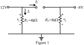
Fig. 11.112
Expert Solution & Answer
Want to see the full answer?
Check out a sample textbook solution
Students have asked these similar questions
Q1. In the AC circuit shown below, all impedances have been obtained at the frequency of the sources. We are interested in finding the phasor current Ix via the node-voltage method. The value of angle = 10xN degrees and the value of current Io = M+1 Amps, where N = 9 and M = 5Need handwritten solution Do not use AI
Solve by pen and paper Do not use AI or chatgpt
Use supermesh method...Do not use AI..Solve by pen and paper
Chapter 11 Solutions
Introductory Circuit Analysis (13th Edition)
Ch. 11 - For the electromagnet in Fig. 11.75: a. Find the...Ch. 11 - For the inductor in Fig. 11.76, find the...Ch. 11 - a. Repeat Problem 2 with a ferromagnetic core with...Ch. 11 - For the inductor in Fig. 11.77, find the...Ch. 11 - An air-core inductor has a total inductance of 4.7...Ch. 11 - What are the inductance and the range of expected...Ch. 11 - If the flux linking a coil of 50 turns changes at...Ch. 11 - Determine the rate of change of flux linking a...Ch. 11 - How many turns does a coil have if 42 mV are...Ch. 11 - Find the voltage induced across a coil of 22 mH if...
Ch. 11 - For the circuit of Fig. 11.78 composed of standard...Ch. 11 - For the circuit in Fig. 11.79 composed of standard...Ch. 11 - For the network of Fig. 11.80. a. Write the...Ch. 11 - Give a supply of 18 V, use standard values to...Ch. 11 - For the circuit in Fig. 11.82: a. Write the...Ch. 11 - In this problem, the effect of reversing the...Ch. 11 - For the network of Fig. 11.84: a. Find the...Ch. 11 - Prob. 18PCh. 11 - Prob. 19PCh. 11 - Prob. 20PCh. 11 - For the network in Fig. 11.88: a. Determine the...Ch. 11 - For the network in Fig. 11.89: a. Write the...Ch. 11 - Prob. 23PCh. 11 - For Fig. 11.91: a. Determine the mathematical...Ch. 11 - For Fig. 11.92: a. Determine the mathematical...Ch. 11 - For the network in Fig. 11.93, the switch is...Ch. 11 - The switch in Fig. 11.94 has been open for a long...Ch. 11 - Prob. 28PCh. 11 - The switch for the network in Fig. 11.96 has been...Ch. 11 - The switch in Fig. 11.97 has been closed for a...Ch. 11 - Given iL=100mA(1e-t/20ms) a. Determine iLatt=1ms....Ch. 11 - a. If the measured current for an inductor during...Ch. 11 - The network in Fig. 11.98 employs a DMM with an...Ch. 11 - Find the waveform for the voltage induced across a...Ch. 11 - Find the waveform for the voltage induced across a...Ch. 11 - Prob. 36PCh. 11 - Find the total inductance of the circuit of Fig....Ch. 11 - Find the total inductance for the network of Fig....Ch. 11 - Reduce the network in Fig. 11.104 to the fewest...Ch. 11 - Reduce the network in Fig. 11.105 to the fewest...Ch. 11 - Reduce the network of Fig. 11.106 to the fewest...Ch. 11 - For the network in Fig. 11.107: a. Write the...Ch. 11 - For the network in Fig. 11.108: a. Write the...Ch. 11 - For the network in Fig. 11.109. a. Find the...Ch. 11 - Find the steady-state currents I1 and I2 for the...Ch. 11 - Find the steady-state currents and voltages for...Ch. 11 - Find the steady-state currents and voltages for...Ch. 11 - Find the indicated steady-state currents and...Ch. 11 - Prob. 49PCh. 11 - Using PSpice or Multisim, verify the results of...Ch. 11 - Using the PSpice or Multisim, find the solution to...Ch. 11 - Using PSpice or Multisim, find the solution to...Ch. 11 - Using PSpice or Multisim, verify the results of...
Additional Engineering Textbook Solutions
Find more solutions based on key concepts
What types of coolant are used in vehicles?
Automotive Technology: Principles, Diagnosis, And Service (6th Edition) (halderman Automotive Series)
Using your text editor, enter (that is, type in) the C++ program shown in Display 1.8. Be certain to type the f...
Problem Solving with C++ (10th Edition)
How is the hydrodynamic entry length defined for flow in a pipe? Is the entry length longer in laminar or turbu...
Fluid Mechanics: Fundamentals and Applications
This optional Google account security feature sends you a message with a code that you must enter, in addition ...
SURVEY OF OPERATING SYSTEMS
Write a summary list of the problem-solving steps identified in the chapter, using your own words.
BASIC BIOMECHANICS
Assume a telephone signal travels through a cable at two-thirds the speed of light. How long does it take the s...
Electric Circuits. (11th Edition)
Knowledge Booster


Learn more about
Need a deep-dive on the concept behind this application? Look no further. Learn more about this topic, electrical-engineering and related others by exploring similar questions and additional content below.Similar questions
- (b). Show how the PAL should be programmed in order to implement each of the following SOP expressions. Use X to indicate an intact fuse. Simplify the expressions, if necessary, to fit the PAL shown (i) Y = ABC + ABC + ABC (ii) Y = ABC + ABC + ABC + ABCarrow_forwardFor the control system Plot root Locus and find the Jain of stability? RIST. K Kp (S+3) S+5 (s+1) s (S+2) (5765+18) 5-1 5²+35+4 * Mathematically, not by Matlab.arrow_forwardNot use ai pleasearrow_forward
- B) Use the results of the autocorrelation function R(T) of the waveform x(t) = A cos(2 fot+o) to find the autocorrelation function R(T) and the average normalized power Py of the waveform y(t) = 5 cos 5t + 10 cos 10t. 12+13 marksarrow_forwardQ2: Obtain the y parameters of the two-port network in the figure below 10 50 50 ww 0.5V2 20 V2 01arrow_forwardProblem 3 In a broadcasting communication system, the transmitter power Pt is 40kW, the channel attenuation is 80dB, and the noise power spectral density S, (f) is 10-10 W/Hz. The message signal has a bandwidth W of 104 Hz. a. Find the output SNR (2) if the modulation is DSB-SC AM b. Find the output SNR if the modulation is SSB AM Narrow_forward
- A random experiment consists of drawing a ball from a box that contains 4 red balls (numbered 1,2,3,4) and 3 black balls numbered (1,2,3). State what outcomes are contained in the following events: a. E₁ = The event that the only balls with an even number are selected b. E2 = The event that only red balls with a number greater than 1 are selected c. E3 The event that only balls with a number less than 3 are selected For reference, an example of a response for such questions is as follows: = Q: E6 The event that only balls with an odd number are selected A: E6 = {R1, R3, B1, B3}. Here R₁ = event that Red ball with number 1 is selected, B3 = Black ball with number 3 is selected.. and so on..arrow_forwardProblem 2 The noise voltage in an electric circuit is modeled as a Gaussian random variable X with a mean equal to zero (m = 0) and a variance equal to 108 (σ² = 10-8). a. What is the probability that the value of the noise exceeds 10-4? P(X > 10-4) = ? b. What is the probability that the noise value is between -2 × 10⁻⁴ and 10-4? P(-2 × 10 4 x < 10-4) = ?arrow_forwardPlease solve it without artificial intelligence on paper and penarrow_forward
arrow_back_ios
SEE MORE QUESTIONS
arrow_forward_ios
Recommended textbooks for you
 Power System Analysis and Design (MindTap Course ...Electrical EngineeringISBN:9781305632134Author:J. Duncan Glover, Thomas Overbye, Mulukutla S. SarmaPublisher:Cengage Learning
Power System Analysis and Design (MindTap Course ...
Electrical Engineering
ISBN:9781305632134
Author:J. Duncan Glover, Thomas Overbye, Mulukutla S. Sarma
Publisher:Cengage Learning
How do Universal Motors work ?; Author: Lesics;https://www.youtube.com/watch?v=0PDRJKz-mqE;License: Standard Youtube License