
Introductory Circuit Analysis (13th Edition)
13th Edition
ISBN: 9780133923605
Author: Robert L. Boylestad
Publisher: PEARSON
expand_more
expand_more
format_list_bulleted
Videos
Textbook Question
Chapter 11, Problem 46P
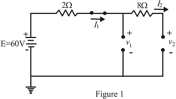
Find the steady-state currents and voltages for the network in Fig. 11.111.
 in Fig. 11.111
Expert Solution & Answer
Want to see the full answer?
Check out a sample textbook solution
Students have asked these similar questions
It states that "in any electrical network, the algebraic sum of the currents meeting at a point or junction is zero".
a. kirchoff's current law
b. kircchoff's current law
c. kirchooff's current law
d. kirchhoff's current law
a) Explain briefly how electricity can be sold to a grid by use solar
energy.
b) Wind farm consist of ten wind turbines with nominal capacity of
2MWper turbine, has a total of 20 MW for farm as a whole, in year
2020, the farm produced a total energy 43416MWH, find a capacity
factor.
2. Syngas enegy content is about.......
a. Two time of natural gas
b. Half of natural gas
c. No energy is available
Chapter 11 Solutions
Introductory Circuit Analysis (13th Edition)
Ch. 11 - For the electromagnet in Fig. 11.75: a. Find the...Ch. 11 - For the inductor in Fig. 11.76, find the...Ch. 11 - a. Repeat Problem 2 with a ferromagnetic core with...Ch. 11 - For the inductor in Fig. 11.77, find the...Ch. 11 - An air-core inductor has a total inductance of 4.7...Ch. 11 - What are the inductance and the range of expected...Ch. 11 - If the flux linking a coil of 50 turns changes at...Ch. 11 - Determine the rate of change of flux linking a...Ch. 11 - How many turns does a coil have if 42 mV are...Ch. 11 - Find the voltage induced across a coil of 22 mH if...
Ch. 11 - For the circuit of Fig. 11.78 composed of standard...Ch. 11 - For the circuit in Fig. 11.79 composed of standard...Ch. 11 - For the network of Fig. 11.80. a. Write the...Ch. 11 - Give a supply of 18 V, use standard values to...Ch. 11 - For the circuit in Fig. 11.82: a. Write the...Ch. 11 - In this problem, the effect of reversing the...Ch. 11 - For the network of Fig. 11.84: a. Find the...Ch. 11 - Prob. 18PCh. 11 - Prob. 19PCh. 11 - Prob. 20PCh. 11 - For the network in Fig. 11.88: a. Determine the...Ch. 11 - For the network in Fig. 11.89: a. Write the...Ch. 11 - Prob. 23PCh. 11 - For Fig. 11.91: a. Determine the mathematical...Ch. 11 - For Fig. 11.92: a. Determine the mathematical...Ch. 11 - For the network in Fig. 11.93, the switch is...Ch. 11 - The switch in Fig. 11.94 has been open for a long...Ch. 11 - Prob. 28PCh. 11 - The switch for the network in Fig. 11.96 has been...Ch. 11 - The switch in Fig. 11.97 has been closed for a...Ch. 11 - Given iL=100mA(1e-t/20ms) a. Determine iLatt=1ms....Ch. 11 - a. If the measured current for an inductor during...Ch. 11 - The network in Fig. 11.98 employs a DMM with an...Ch. 11 - Find the waveform for the voltage induced across a...Ch. 11 - Find the waveform for the voltage induced across a...Ch. 11 - Prob. 36PCh. 11 - Find the total inductance of the circuit of Fig....Ch. 11 - Find the total inductance for the network of Fig....Ch. 11 - Reduce the network in Fig. 11.104 to the fewest...Ch. 11 - Reduce the network in Fig. 11.105 to the fewest...Ch. 11 - Reduce the network of Fig. 11.106 to the fewest...Ch. 11 - For the network in Fig. 11.107: a. Write the...Ch. 11 - For the network in Fig. 11.108: a. Write the...Ch. 11 - For the network in Fig. 11.109. a. Find the...Ch. 11 - Find the steady-state currents I1 and I2 for the...Ch. 11 - Find the steady-state currents and voltages for...Ch. 11 - Find the steady-state currents and voltages for...Ch. 11 - Find the indicated steady-state currents and...Ch. 11 - Prob. 49PCh. 11 - Using PSpice or Multisim, verify the results of...Ch. 11 - Using the PSpice or Multisim, find the solution to...Ch. 11 - Using PSpice or Multisim, find the solution to...Ch. 11 - Using PSpice or Multisim, verify the results of...
Knowledge Booster


Learn more about
Need a deep-dive on the concept behind this application? Look no further. Learn more about this topic, electrical-engineering and related others by exploring similar questions and additional content below.Similar questions
- Calculate the steady state value of the I and the V1 and V2.arrow_forwardUse Kirchhoff's Voltage Law and Kirchhoff's Current Law to calculate the following dataarrow_forwardFor the circuit in fig .11.82 A. Write the mathematical expressions for the current IL and the voltage Vl following the closing of the switch. B. Sketch the waveform of iL and VL for the entire period from initial value to steady-state level.arrow_forward
- From the circuit determine the current through the 10 kilo-ohm resistor at terminals a-b, micro-ampere. a. 238.0952 b. 692.6407 c. 21.6450 d. 123.2412 e. None of the abovearrow_forwardThe real power delivered by a source to two impedances, Z1=4+j5 and Z2=10 connected in parallel, is 1000 W. Determine (a) the real power absorbed by each of the impedances and (b) the source current.arrow_forwardGet the value of IB . Show complete solution.arrow_forward
- Variation of which of the following parameter is not consider as power quality problem for industry?VoltageCurrentPowerFrequencyarrow_forwardObtain the transformation ratio between voltages and currents in each of the following casesarrow_forward(Note that the a,b,c,d are branches)1. Measure and record the potential difference for the following branches. Be mindful of the algebraic sign. a-b a-c b-c c-d a-d b-d And using the measured potential difference values, compute for the algebraic sum of the potential difference for the following electrical loops. Indicate the equation with values as well. abca abdca acda abcda acbdaarrow_forward
- Determine the current Ic, current at the resistor, and current supplied by the voltage source. Note: you must put the imaginary part of the reactances and its signarrow_forwardfind the area of shell selbm & = oT a.410 T mz b.300 Ti mt C. 2001T m²arrow_forwardPlease write the solution clearlyarrow_forward
arrow_back_ios
SEE MORE QUESTIONS
arrow_forward_ios
Recommended textbooks for you
 Power System Analysis and Design (MindTap Course ...Electrical EngineeringISBN:9781305632134Author:J. Duncan Glover, Thomas Overbye, Mulukutla S. SarmaPublisher:Cengage Learning
Power System Analysis and Design (MindTap Course ...
Electrical Engineering
ISBN:9781305632134
Author:J. Duncan Glover, Thomas Overbye, Mulukutla S. Sarma
Publisher:Cengage Learning
Lesson 2 - Source Transformations, Part 2 (Engineering Circuits); Author: Math and Science;https://www.youtube.com/watch?v=7gno74RhVGQ;License: Standard Youtube License