
Introductory Circuit Analysis (13th Edition)
13th Edition
ISBN: 9780133923605
Author: Robert L. Boylestad
Publisher: PEARSON
expand_more
expand_more
format_list_bulleted
Concept explainers
Videos
Textbook Question
Chapter 11, Problem 33P
The network in Fig. 11.98 employs a DMM with an internal resistance of 10 M
a. Find the voltage across the coil the instant after the switch is closed.
b. What is the final value of the current iL?
c. How much time must pass before L reaches 10
d. What is the voltmeter reading at
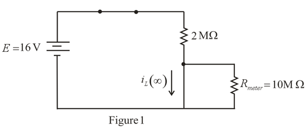
Fig. 11.98
Expert Solution & Answer
Want to see the full answer?
Check out a sample textbook solution
Students have asked these similar questions
11. For the circuit below composed of standard values:
• Determine the time constant.
• Write the mathematical expression for the current i after the switch is closed.
• Repeat part (b) for vL and vr
• Determine i and vi at one, three, and five time constants.
Sketch the waveforms of i, VL, and VR.
+ UR
R
20 kN
EE 40 V
470 mH
UL
ll
120 *
8F
what is the T ?
b. what is the voitage capactor apter 10 sec?
c. How many
a.
time constants will it toake for tue
do Itage to reach 8o v.?
d. Given that the capacator is
Fully Charged, how
time constants will it be to reah
many
GOV
TOPIC: Fundamentals of Alternating Current Powers
Give illustration and a step by step solution. Final answer must be in 4 decimal places.
1. A load takes 55kW at 70% power factor lagging from a 240V, 50Hz supply. If the supply is made 60Hz, with the voltage remaining the same, what will be the kW load at 60Hz?
2. An inductive coil takes a current of 2A and consumes 160W when connected to a 240V supply. A second coil when connected across the same supply takes 3A and 500W. Find the total power when the two coils are connected in series to the supply.
3. A series RC circuit is connected to 230V, 60Hz source. If the power taken by the circuit is 4,800W and the voltage drop across the resistor is 115V, calculate the capacitance of the
capacitor.
Thank You in advance!
Chapter 11 Solutions
Introductory Circuit Analysis (13th Edition)
Ch. 11 - For the electromagnet in Fig. 11.75: a. Find the...Ch. 11 - For the inductor in Fig. 11.76, find the...Ch. 11 - a. Repeat Problem 2 with a ferromagnetic core with...Ch. 11 - For the inductor in Fig. 11.77, find the...Ch. 11 - An air-core inductor has a total inductance of 4.7...Ch. 11 - What are the inductance and the range of expected...Ch. 11 - If the flux linking a coil of 50 turns changes at...Ch. 11 - Determine the rate of change of flux linking a...Ch. 11 - How many turns does a coil have if 42 mV are...Ch. 11 - Find the voltage induced across a coil of 22 mH if...
Ch. 11 - For the circuit of Fig. 11.78 composed of standard...Ch. 11 - For the circuit in Fig. 11.79 composed of standard...Ch. 11 - For the network of Fig. 11.80. a. Write the...Ch. 11 - Give a supply of 18 V, use standard values to...Ch. 11 - For the circuit in Fig. 11.82: a. Write the...Ch. 11 - In this problem, the effect of reversing the...Ch. 11 - For the network of Fig. 11.84: a. Find the...Ch. 11 - Prob. 18PCh. 11 - Prob. 19PCh. 11 - Prob. 20PCh. 11 - For the network in Fig. 11.88: a. Determine the...Ch. 11 - For the network in Fig. 11.89: a. Write the...Ch. 11 - Prob. 23PCh. 11 - For Fig. 11.91: a. Determine the mathematical...Ch. 11 - For Fig. 11.92: a. Determine the mathematical...Ch. 11 - For the network in Fig. 11.93, the switch is...Ch. 11 - The switch in Fig. 11.94 has been open for a long...Ch. 11 - Prob. 28PCh. 11 - The switch for the network in Fig. 11.96 has been...Ch. 11 - The switch in Fig. 11.97 has been closed for a...Ch. 11 - Given iL=100mA(1e-t/20ms) a. Determine iLatt=1ms....Ch. 11 - a. If the measured current for an inductor during...Ch. 11 - The network in Fig. 11.98 employs a DMM with an...Ch. 11 - Find the waveform for the voltage induced across a...Ch. 11 - Find the waveform for the voltage induced across a...Ch. 11 - Prob. 36PCh. 11 - Find the total inductance of the circuit of Fig....Ch. 11 - Find the total inductance for the network of Fig....Ch. 11 - Reduce the network in Fig. 11.104 to the fewest...Ch. 11 - Reduce the network in Fig. 11.105 to the fewest...Ch. 11 - Reduce the network of Fig. 11.106 to the fewest...Ch. 11 - For the network in Fig. 11.107: a. Write the...Ch. 11 - For the network in Fig. 11.108: a. Write the...Ch. 11 - For the network in Fig. 11.109. a. Find the...Ch. 11 - Find the steady-state currents I1 and I2 for the...Ch. 11 - Find the steady-state currents and voltages for...Ch. 11 - Find the steady-state currents and voltages for...Ch. 11 - Find the indicated steady-state currents and...Ch. 11 - Prob. 49PCh. 11 - Using PSpice or Multisim, verify the results of...Ch. 11 - Using the PSpice or Multisim, find the solution to...Ch. 11 - Using PSpice or Multisim, find the solution to...Ch. 11 - Using PSpice or Multisim, verify the results of...
Knowledge Booster


Learn more about
Need a deep-dive on the concept behind this application? Look no further. Learn more about this topic, electrical-engineering and related others by exploring similar questions and additional content below.Similar questions
- The inductive reactance (in ohms) of a 0.06 H coil connected to a 120-V, 60-Hz source is Blank 1. The resulting value must be rounded off to the nearest thousandths. Blank 1 Add your answerarrow_forward1. A coil of 2000 turns with a 100-mA current has a length of 0.2 m. (a) Calculate H in ampere-turns per the mmf in ampere-turns. (b) Calculate the field intensity meter.arrow_forward6. A copper coil has a resistance of 200 ohms when its mean temperature is s 0 degree centigrade. Calculate the resistance of the coil when its mean temperature is 80 degree centigrade. Temperature coefficient of copper is 0.004041 centigrade1arrow_forward
- An e.m.f. of 16 volts is induced in a coil of inductance 4H. The rate of change of current must be (a) 64 A/s (b) 32 A/s (c) 16 A/s (d) 4 A/sarrow_forward23 - When a voltage is applied to a coil or the applied voltage is cut off, the current of the circuit does not rise to its normal value or drop to zero. The current becomes stable after a certain period of time. This time depends on what?A) NoneB) Inductance of the coil (L)C) ohmic resistance of the coil (R)D) Hardness of the CoilE) to the weight of the coilarrow_forwardA voltage-multiplier has a Vm = 60 V peak sinusoidal secondary voltage. During the positive half-cycle, D1 conducts and D2 is cut-off, charging C1 up to what voltage level? C1 HE (A) OV B) 60 V V Ⓒ120 V (D) 180 V Vp 1:1 Vm = 60 V D1 D2 не C2 Ideal diodes C3 HE D3 D4 C4 :arrow_forward
- 22 1852 172 12 52 The circuit shown in Figure has been connected for a long time. What is the potential difference across the 22-2 resistor? O A) 13.5 V O B) 32.4 V C) 72 V O D) 58.5 V E) 39.6 Varrow_forwardThe hot water heater in our homes is an example of closed-loop system O Open-loop system none of the abovearrow_forward23 - When a voltage is applied to a coil or the applied voltage is cut off, the current of the circuit does not rise to its normal value or drop to zero. The current becomes stable after a certain period of time. This time depends on what?A) NoneB) Inductance of the coil (L)C) ohmic resistance of the coil (R)D) Hardness of the Coilarrow_forward
- voltmeter is connected in series on the element when we are taking the reading of the voltage Select the correct response: True Falsearrow_forwardI need help with (d) . Thanks 1. Consider a half-wave rectifier circuit with a resistive load of 25 Ωand a 60 Hz ac source of 110V rms.(a) Determine v0(t) and i0(t)(b) Calculate the rms values of v0(t) and i0(t)(c) Calculate the average power delivered to the load(d) Repeat questions a , b, and c to the full wave rectifier of Figure below with R-load and thesame source and load parametersarrow_forward11. For the circuit below, determine the voltages across each component. 1k 50 mH50 nF 1 sin2pi1000t 1 cos2pi1000tarrow_forward
arrow_back_ios
SEE MORE QUESTIONS
arrow_forward_ios
Recommended textbooks for you
 Delmar's Standard Textbook Of ElectricityElectrical EngineeringISBN:9781337900348Author:Stephen L. HermanPublisher:Cengage Learning
 Electricity for Refrigeration, Heating, and Air C...Mechanical EngineeringISBN:9781337399128Author:Russell E. SmithPublisher:Cengage Learning
Delmar's Standard Textbook Of Electricity
Electrical Engineering
ISBN:9781337900348
Author:Stephen L. Herman
Publisher:Cengage Learning
Electricity for Refrigeration, Heating, and Air C...
Mechanical Engineering
ISBN:9781337399128
Author:Russell E. Smith
Publisher:Cengage Learning
How Electric Motors Work - 3 phase AC induction motors ac motor; Author: The Engineering Mindset;https://www.youtube.com/watch?v=59HBoIXzX_c;License: Standard Youtube License