
Introductory Circuit Analysis (13th Edition)
13th Edition
ISBN: 9780133923605
Author: Robert L. Boylestad
Publisher: PEARSON
expand_more
expand_more
format_list_bulleted
Videos
Textbook Question
Chapter 11, Problem 13P
For the network of Fig. 11.80.
a. Write the expression for the voltage vL after the switch is closed.
b. Sketch the waveform for the source current after the switch is closed.
c. How long after the switch is closed can we assume the inductor is acting like a short circuit?
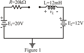
Fig. 11.80
Expert Solution & Answer

Trending nowThis is a popular solution!

Students have asked these similar questions
The diagram shows an inductor that is part of a circuit. The direction of the emf induced in the inductor is indicated. Which of the following is possible?
elle
O a. The current is increasing and leftward
O b. The current is constant and leftward.
O c.
None of these.
O d. The current is increasing and rightward.
O e.
The current is constant and rightward.
A 70-Vac source has the following waveform. Determine:a. equation of the waveform (in time domain)b. the instantaneous voltage when t = 120 msc. the angle (1st occurrence) after t = 0 when the voltage is +80 Vd. the time (2nd occurrence) after t = 0 when the voltage is –10 V
AC
15. What would the equivalent resistance be of a 159 uF capacitor?
16. What is the RMS voltage of a circuit if the peak voltage is 170 volts?
17. If the RMS voltage is 240 volts AC, what is the peak voltage?
18. What is the formula for finding an inductors equivalent resistance?
19. What is the equivalent resistance of an inductor with 0.17 henrys?
20. What is the symbol of an AC power source?
21. What is the equivalent inductance of a parallel circuit with a 0.01L, 0.02L, and 1.7L inductor?
22. What is the equivalent inductance of a series circuit with a 0.03L, 0.04L, and 1.6L inductor?
23. A transformer with a primary voltage of 480 volts and a turns ratio of 2:1 will have what
secondary voltage?
24. A Power Network is comprised of what three components?
25. What is the main difference between a fuse and a circuit breaker?
Chapter 11 Solutions
Introductory Circuit Analysis (13th Edition)
Ch. 11 - For the electromagnet in Fig. 11.75: a. Find the...Ch. 11 - For the inductor in Fig. 11.76, find the...Ch. 11 - a. Repeat Problem 2 with a ferromagnetic core with...Ch. 11 - For the inductor in Fig. 11.77, find the...Ch. 11 - An air-core inductor has a total inductance of 4.7...Ch. 11 - What are the inductance and the range of expected...Ch. 11 - If the flux linking a coil of 50 turns changes at...Ch. 11 - Determine the rate of change of flux linking a...Ch. 11 - How many turns does a coil have if 42 mV are...Ch. 11 - Find the voltage induced across a coil of 22 mH if...
Ch. 11 - For the circuit of Fig. 11.78 composed of standard...Ch. 11 - For the circuit in Fig. 11.79 composed of standard...Ch. 11 - For the network of Fig. 11.80. a. Write the...Ch. 11 - Give a supply of 18 V, use standard values to...Ch. 11 - For the circuit in Fig. 11.82: a. Write the...Ch. 11 - In this problem, the effect of reversing the...Ch. 11 - For the network of Fig. 11.84: a. Find the...Ch. 11 - Prob. 18PCh. 11 - Prob. 19PCh. 11 - Prob. 20PCh. 11 - For the network in Fig. 11.88: a. Determine the...Ch. 11 - For the network in Fig. 11.89: a. Write the...Ch. 11 - Prob. 23PCh. 11 - For Fig. 11.91: a. Determine the mathematical...Ch. 11 - For Fig. 11.92: a. Determine the mathematical...Ch. 11 - For the network in Fig. 11.93, the switch is...Ch. 11 - The switch in Fig. 11.94 has been open for a long...Ch. 11 - Prob. 28PCh. 11 - The switch for the network in Fig. 11.96 has been...Ch. 11 - The switch in Fig. 11.97 has been closed for a...Ch. 11 - Given iL=100mA(1e-t/20ms) a. Determine iLatt=1ms....Ch. 11 - a. If the measured current for an inductor during...Ch. 11 - The network in Fig. 11.98 employs a DMM with an...Ch. 11 - Find the waveform for the voltage induced across a...Ch. 11 - Find the waveform for the voltage induced across a...Ch. 11 - Prob. 36PCh. 11 - Find the total inductance of the circuit of Fig....Ch. 11 - Find the total inductance for the network of Fig....Ch. 11 - Reduce the network in Fig. 11.104 to the fewest...Ch. 11 - Reduce the network in Fig. 11.105 to the fewest...Ch. 11 - Reduce the network of Fig. 11.106 to the fewest...Ch. 11 - For the network in Fig. 11.107: a. Write the...Ch. 11 - For the network in Fig. 11.108: a. Write the...Ch. 11 - For the network in Fig. 11.109. a. Find the...Ch. 11 - Find the steady-state currents I1 and I2 for the...Ch. 11 - Find the steady-state currents and voltages for...Ch. 11 - Find the steady-state currents and voltages for...Ch. 11 - Find the indicated steady-state currents and...Ch. 11 - Prob. 49PCh. 11 - Using PSpice or Multisim, verify the results of...Ch. 11 - Using the PSpice or Multisim, find the solution to...Ch. 11 - Using PSpice or Multisim, find the solution to...Ch. 11 - Using PSpice or Multisim, verify the results of...
Knowledge Booster


Learn more about
Need a deep-dive on the concept behind this application? Look no further. Learn more about this topic, electrical-engineering and related others by exploring similar questions and additional content below.Similar questions
- 1. A 70-Vac source has the following waveform. Determine: 50 ms- 180 V h) equation of the waveform (in time domain) i) the instantaneous voltage when t = 120 ms j) the angle (1st occurrence) after t = 0 when the voltage is +80 V k) the time (2nd occurrence) after t = 0 when the voltage is –10 Varrow_forwardA 70-Vac source has the following waveform.Determine:a. the instantaneous voltage when t = 120 msb. the angle (1st occurrence) after t = 0 when the voltage is +80 Vc. the time (2nd occurrence) after t = 0 when the voltage is –10 Varrow_forwardAn air filled parallel-plate capacitor is connected to a 12 Volts battery, the battery is disconnected when it is fully charged to 7.3 nC. The separation distance between the plates is d1= 8 cm. Now, If the plates are moved to a new distance d233 cm. the new energy stored in the capacitor is O a. 13.14 nJ O b. 8.21 nJ O c. 1.64 nJ O d. 10.96 nJ O e. 5.47 nJ O f. 16.42 nJarrow_forward
- An e.m.f of 25 volts is induced in a coil of inductance 50 mH, then the rate of change of current is 5 A/sec 500 A/sec 50 A/sec 0.5 A/secarrow_forwardA series circuit conducting of a 30-uf capacitor and a 0.155-henry inductor is connected to a 120-volt 60-cycle source. If a variable inductor is substitute instead, what should be its value if an equal current is to lag behind the voltage? Assume all other conditions remain unchangedarrow_forwardWhat do you think will happen to the current if the frequency is adjusted higher in the pure inductance experiment? and what will happen to the current if the frequency is adjusted lower in pure inductance experiment? explain why pleasearrow_forward
- A coil has a resistance of 18 when it mean temp is from 20o C to 50o C. Find its mean temp rise when its resistance is 21 and the surrounding temp is 15o C. A potential difference of 250 V is applied to a copper field coil at a temp of 15o C and the current is 5A. What will be the mean temp of the coil when the current has fallen to 3.91 A, the applied voltage being the same as before.arrow_forward17 A Capacitor 10 stores 0124 Cat volts. Its Capacitance is ? Aarrow_forwardCalculate Fermi Function in the following scenarios: Energy level at positive infinityarrow_forward
- A coil of inductance 50 mH and resistance 5 ohm is connected to a 110V, d.c. supply. Determine the final value of current, the value of current after 4 ms, the value of the voltage across the resistor after 6 ms, the value of the voltage across the inductance after 6 ms, and the time when the current reaches 15A.arrow_forwardWhere is electrical energy stored in an inductor? O In the electric field surrounding its coils. O In the magnetic field surrounding its coils. O In both the electric and magnetic field surrounding its coils. O An inductor never stores electrical energy.arrow_forwardFor the network shown in figure (3), if the switch is closed for 2usec and then opened for Susec, find mathematical expressions for vi and in of both periods of time and then plot the waveforms of vL and i as a function of time.arrow_forward
arrow_back_ios
SEE MORE QUESTIONS
arrow_forward_ios
Recommended textbooks for you
 Introductory Circuit Analysis (13th Edition)Electrical EngineeringISBN:9780133923605Author:Robert L. BoylestadPublisher:PEARSON
 Delmar's Standard Textbook Of ElectricityElectrical EngineeringISBN:9781337900348Author:Stephen L. HermanPublisher:Cengage Learning
 Programmable Logic ControllersElectrical EngineeringISBN:9780073373843Author:Frank D. PetruzellaPublisher:McGraw-Hill Education
 Fundamentals of Electric CircuitsElectrical EngineeringISBN:9780078028229Author:Charles K Alexander, Matthew SadikuPublisher:McGraw-Hill Education
 Electric Circuits. (11th Edition)Electrical EngineeringISBN:9780134746968Author:James W. Nilsson, Susan RiedelPublisher:PEARSON
 Engineering ElectromagneticsElectrical EngineeringISBN:9780078028151Author:Hayt, William H. (william Hart), Jr, BUCK, John A.Publisher:Mcgraw-hill Education,
Introductory Circuit Analysis (13th Edition)
Electrical Engineering
ISBN:9780133923605
Author:Robert L. Boylestad
Publisher:PEARSON
Delmar's Standard Textbook Of Electricity
Electrical Engineering
ISBN:9781337900348
Author:Stephen L. Herman
Publisher:Cengage Learning
Programmable Logic Controllers
Electrical Engineering
ISBN:9780073373843
Author:Frank D. Petruzella
Publisher:McGraw-Hill Education
Fundamentals of Electric Circuits
Electrical Engineering
ISBN:9780078028229
Author:Charles K Alexander, Matthew Sadiku
Publisher:McGraw-Hill Education
Electric Circuits. (11th Edition)
Electrical Engineering
ISBN:9780134746968
Author:James W. Nilsson, Susan Riedel
Publisher:PEARSON
Engineering Electromagnetics
Electrical Engineering
ISBN:9780078028151
Author:Hayt, William H. (william Hart), Jr, BUCK, John A.
Publisher:Mcgraw-hill Education,
How do Universal Motors work ?; Author: Lesics;https://www.youtube.com/watch?v=0PDRJKz-mqE;License: Standard Youtube License