
Introductory Circuit Analysis (13th Edition)
13th Edition
ISBN: 9780133923605
Author: Robert L. Boylestad
Publisher: PEARSON
expand_more
expand_more
format_list_bulleted
Videos
Textbook Question
Chapter 11, Problem 22P
For the network in Fig. 11.89:
a. Write the mathematical expression for the current iL and the voltageivL following the closing of the switch.
b. Determine the mathematical expressions for iL and vL if the switch is opened after a period of five time constants has passed.
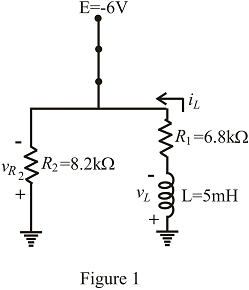
c. Sketch the waveforms of iL and vL for the time periods defined by parts (a) and (b).
d. Sketch the waveform for the voltage across R2 for the same period of time encompassed by iL and vL Take careful note of the defined polarities and directions in Fig. 11.89.
Expert Solution & Answer
Want to see the full answer?
Check out a sample textbook solution
Students have asked these similar questions
8. Liquids with solid impurities
a) Have higher dielectrie strength
b) Of large size have higher dielectric strength
c) Have lower dielectric strength as compared to pure liquids
d) None of the above
9. Peak to peak ripple is defined as
a) the difference between average de voltage and peak value
b) the difference between maximum and minimum de voltage
c) the difference between maximum ac and average dc voltages
d) the difference between ac (rms) and average de voltages
10. In a Cockroft-Walton circuit, input voltage 100 kV load current 25 mA, supply
frequency 100 Hz, each capacitor 10 nF. The optimum no. of stages for maximum
output voltage is
a) 1
b) 2
c) 10
d) 35
Identify the statement from the following when the
inductance can have high value.
a. All the given options
O b. If the number of turns of the wire is more
O c. If the length of the wire is longer
O d. If the cross-sectional area is less
The effective voltage of alternating current is __________ times its highest or peak voltage.
Select one:
A. .9
B. .707
C. 100%
D. E=IXR
Chapter 11 Solutions
Introductory Circuit Analysis (13th Edition)
Ch. 11 - For the electromagnet in Fig. 11.75: a. Find the...Ch. 11 - For the inductor in Fig. 11.76, find the...Ch. 11 - a. Repeat Problem 2 with a ferromagnetic core with...Ch. 11 - For the inductor in Fig. 11.77, find the...Ch. 11 - An air-core inductor has a total inductance of 4.7...Ch. 11 - What are the inductance and the range of expected...Ch. 11 - If the flux linking a coil of 50 turns changes at...Ch. 11 - Determine the rate of change of flux linking a...Ch. 11 - How many turns does a coil have if 42 mV are...Ch. 11 - Find the voltage induced across a coil of 22 mH if...
Ch. 11 - For the circuit of Fig. 11.78 composed of standard...Ch. 11 - For the circuit in Fig. 11.79 composed of standard...Ch. 11 - For the network of Fig. 11.80. a. Write the...Ch. 11 - Give a supply of 18 V, use standard values to...Ch. 11 - For the circuit in Fig. 11.82: a. Write the...Ch. 11 - In this problem, the effect of reversing the...Ch. 11 - For the network of Fig. 11.84: a. Find the...Ch. 11 - Prob. 18PCh. 11 - Prob. 19PCh. 11 - Prob. 20PCh. 11 - For the network in Fig. 11.88: a. Determine the...Ch. 11 - For the network in Fig. 11.89: a. Write the...Ch. 11 - Prob. 23PCh. 11 - For Fig. 11.91: a. Determine the mathematical...Ch. 11 - For Fig. 11.92: a. Determine the mathematical...Ch. 11 - For the network in Fig. 11.93, the switch is...Ch. 11 - The switch in Fig. 11.94 has been open for a long...Ch. 11 - Prob. 28PCh. 11 - The switch for the network in Fig. 11.96 has been...Ch. 11 - The switch in Fig. 11.97 has been closed for a...Ch. 11 - Given iL=100mA(1e-t/20ms) a. Determine iLatt=1ms....Ch. 11 - a. If the measured current for an inductor during...Ch. 11 - The network in Fig. 11.98 employs a DMM with an...Ch. 11 - Find the waveform for the voltage induced across a...Ch. 11 - Find the waveform for the voltage induced across a...Ch. 11 - Prob. 36PCh. 11 - Find the total inductance of the circuit of Fig....Ch. 11 - Find the total inductance for the network of Fig....Ch. 11 - Reduce the network in Fig. 11.104 to the fewest...Ch. 11 - Reduce the network in Fig. 11.105 to the fewest...Ch. 11 - Reduce the network of Fig. 11.106 to the fewest...Ch. 11 - For the network in Fig. 11.107: a. Write the...Ch. 11 - For the network in Fig. 11.108: a. Write the...Ch. 11 - For the network in Fig. 11.109. a. Find the...Ch. 11 - Find the steady-state currents I1 and I2 for the...Ch. 11 - Find the steady-state currents and voltages for...Ch. 11 - Find the steady-state currents and voltages for...Ch. 11 - Find the indicated steady-state currents and...Ch. 11 - Prob. 49PCh. 11 - Using PSpice or Multisim, verify the results of...Ch. 11 - Using the PSpice or Multisim, find the solution to...Ch. 11 - Using PSpice or Multisim, find the solution to...Ch. 11 - Using PSpice or Multisim, verify the results of...
Knowledge Booster


Learn more about
Need a deep-dive on the concept behind this application? Look no further. Learn more about this topic, electrical-engineering and related others by exploring similar questions and additional content below.Similar questions
- 2.)What is the difference between Ampere's law and Biot-Savart's law?arrow_forwardHi please help me sketch the waveforms of voltage and current for these conditions. I ahven't understand our discussion in class pls help mearrow_forward25/ Identify the statement from the following when the inductance can have low value. a. If the number of turns of the wire is less b. If the cross-sectional area is lesser c. If the length of the wire is longer d. All the given optionsarrow_forward
- How temperature effect conductivity? Explain with the help of following equation. m e'n7'arrow_forwardWhich of the following is NOT a variable in voltametric methods? A. How the current is applied B. How the potential is applied C. The inclusion of convection D. All the above E. Type of working electrodearrow_forwardDiscuss the difference between Alternating Current (AC) and Direct Current (DC)arrow_forward
- 4. An alternating voltage is represented by the expression v= 35 sin (314.2 t) volt. Determine, i) the maximum value, ii) the frequency, iii) the period of the waveform, and iv) the value 3.5 ms after it passes through zero, going positive. (b) i. Explain the types of semiconductors and the classifications of the semiconductor materials. ii. With the aid of a diagram, explain the formation of the P and N types of semiconductor.arrow_forwardaloulated m O1 the value you Up = A cos wt +1o Calaulate maarli)-min(i) =? Use constant voltage drop mad. Don7 to write units. . - 3.7V forgetarrow_forwardİNGİLİZCE TÜRKÇE RUSÇA In a semiconductor crystal, atoms are held together as follows: Please choose one: a. gravitational forces b. covalent bonds C. interaction of valence electrons D. answers A., B. and C. 92/5000 13:30 30.04.2021arrow_forward
arrow_back_ios
SEE MORE QUESTIONS
arrow_forward_ios
Recommended textbooks for you
 Introductory Circuit Analysis (13th Edition)Electrical EngineeringISBN:9780133923605Author:Robert L. BoylestadPublisher:PEARSON
 Delmar's Standard Textbook Of ElectricityElectrical EngineeringISBN:9781337900348Author:Stephen L. HermanPublisher:Cengage Learning
 Programmable Logic ControllersElectrical EngineeringISBN:9780073373843Author:Frank D. PetruzellaPublisher:McGraw-Hill Education
 Fundamentals of Electric CircuitsElectrical EngineeringISBN:9780078028229Author:Charles K Alexander, Matthew SadikuPublisher:McGraw-Hill Education
 Electric Circuits. (11th Edition)Electrical EngineeringISBN:9780134746968Author:James W. Nilsson, Susan RiedelPublisher:PEARSON
 Engineering ElectromagneticsElectrical EngineeringISBN:9780078028151Author:Hayt, William H. (william Hart), Jr, BUCK, John A.Publisher:Mcgraw-hill Education,
Introductory Circuit Analysis (13th Edition)
Electrical Engineering
ISBN:9780133923605
Author:Robert L. Boylestad
Publisher:PEARSON
Delmar's Standard Textbook Of Electricity
Electrical Engineering
ISBN:9781337900348
Author:Stephen L. Herman
Publisher:Cengage Learning
Programmable Logic Controllers
Electrical Engineering
ISBN:9780073373843
Author:Frank D. Petruzella
Publisher:McGraw-Hill Education
Fundamentals of Electric Circuits
Electrical Engineering
ISBN:9780078028229
Author:Charles K Alexander, Matthew Sadiku
Publisher:McGraw-Hill Education
Electric Circuits. (11th Edition)
Electrical Engineering
ISBN:9780134746968
Author:James W. Nilsson, Susan Riedel
Publisher:PEARSON
Engineering Electromagnetics
Electrical Engineering
ISBN:9780078028151
Author:Hayt, William H. (william Hart), Jr, BUCK, John A.
Publisher:Mcgraw-hill Education,
How do Universal Motors work ?; Author: Lesics;https://www.youtube.com/watch?v=0PDRJKz-mqE;License: Standard Youtube License