
Introductory Circuit Analysis (13th Edition)
13th Edition
ISBN: 9780133923605
Author: Robert L. Boylestad
Publisher: PEARSON
expand_more
expand_more
format_list_bulleted
Videos
Textbook Question
Chapter 11, Problem 11P
For the circuit of Fig. 11.78 composed of standard values:
a. Determine the time constant.
b. Write the mathematical expression for the current iL after the switch is closed.
c. Repeat part (b) for VL and VR
d. Determine iL and VL at one, three, and five time constants.
e. Sketch the waveforms of iL, vL and vR.
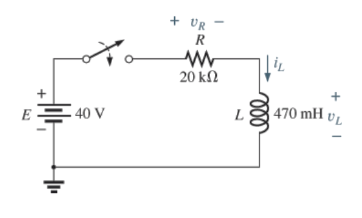
Fig. 11.78
Expert Solution & Answer
Want to see the full answer?
Check out a sample textbook solution
Students have asked these similar questions
Q: - Consider the circuit in Figure
a) What type of circuit is this?
b) Find and Sketch the voltage
waveform across RL, assume
the diodes are practical.
4:1
D,
120 V rms
c) If
sin wave with
100µf
connected in parallel with the
resistor, calculate the ripple
сарacitor
is
60 HZ
1.0 kN
D2
factor
lllee
lelll
A three phase full wave rectifier is shown below. The input phase voltage peak is Vm=311.128 V. The load is
purely resistive of value 52. The DC and RMS output voltages are respectively equal to:
Secondary
太D太D,太D,
太D。太De太D,
b.
Select one:
O a.
180V, 240.2V
O b. 514.6V, 515.04V
O c.
180V, 197.2V
O d. 220V, 249.2V
Problem 1.
Consider a half-wave rectifier circuit with a resistive load of 25 Ωand a 60 Hz ac source of 110V rms. Determine v0(t) and i0(t), the rms values of v0(t) and i0(t), the average power delivered to the load .
Chapter 11 Solutions
Introductory Circuit Analysis (13th Edition)
Ch. 11 - For the electromagnet in Fig. 11.75: a. Find the...Ch. 11 - For the inductor in Fig. 11.76, find the...Ch. 11 - a. Repeat Problem 2 with a ferromagnetic core with...Ch. 11 - For the inductor in Fig. 11.77, find the...Ch. 11 - An air-core inductor has a total inductance of 4.7...Ch. 11 - What are the inductance and the range of expected...Ch. 11 - If the flux linking a coil of 50 turns changes at...Ch. 11 - Determine the rate of change of flux linking a...Ch. 11 - How many turns does a coil have if 42 mV are...Ch. 11 - Find the voltage induced across a coil of 22 mH if...
Ch. 11 - For the circuit of Fig. 11.78 composed of standard...Ch. 11 - For the circuit in Fig. 11.79 composed of standard...Ch. 11 - For the network of Fig. 11.80. a. Write the...Ch. 11 - Give a supply of 18 V, use standard values to...Ch. 11 - For the circuit in Fig. 11.82: a. Write the...Ch. 11 - In this problem, the effect of reversing the...Ch. 11 - For the network of Fig. 11.84: a. Find the...Ch. 11 - Prob. 18PCh. 11 - Prob. 19PCh. 11 - Prob. 20PCh. 11 - For the network in Fig. 11.88: a. Determine the...Ch. 11 - For the network in Fig. 11.89: a. Write the...Ch. 11 - Prob. 23PCh. 11 - For Fig. 11.91: a. Determine the mathematical...Ch. 11 - For Fig. 11.92: a. Determine the mathematical...Ch. 11 - For the network in Fig. 11.93, the switch is...Ch. 11 - The switch in Fig. 11.94 has been open for a long...Ch. 11 - Prob. 28PCh. 11 - The switch for the network in Fig. 11.96 has been...Ch. 11 - The switch in Fig. 11.97 has been closed for a...Ch. 11 - Given iL=100mA(1e-t/20ms) a. Determine iLatt=1ms....Ch. 11 - a. If the measured current for an inductor during...Ch. 11 - The network in Fig. 11.98 employs a DMM with an...Ch. 11 - Find the waveform for the voltage induced across a...Ch. 11 - Find the waveform for the voltage induced across a...Ch. 11 - Prob. 36PCh. 11 - Find the total inductance of the circuit of Fig....Ch. 11 - Find the total inductance for the network of Fig....Ch. 11 - Reduce the network in Fig. 11.104 to the fewest...Ch. 11 - Reduce the network in Fig. 11.105 to the fewest...Ch. 11 - Reduce the network of Fig. 11.106 to the fewest...Ch. 11 - For the network in Fig. 11.107: a. Write the...Ch. 11 - For the network in Fig. 11.108: a. Write the...Ch. 11 - For the network in Fig. 11.109. a. Find the...Ch. 11 - Find the steady-state currents I1 and I2 for the...Ch. 11 - Find the steady-state currents and voltages for...Ch. 11 - Find the steady-state currents and voltages for...Ch. 11 - Find the indicated steady-state currents and...Ch. 11 - Prob. 49PCh. 11 - Using PSpice or Multisim, verify the results of...Ch. 11 - Using the PSpice or Multisim, find the solution to...Ch. 11 - Using PSpice or Multisim, find the solution to...Ch. 11 - Using PSpice or Multisim, verify the results of...
Knowledge Booster


Learn more about
Need a deep-dive on the concept behind this application? Look no further. Learn more about this topic, electrical-engineering and related others by exploring similar questions and additional content below.Similar questions
- Which of the following is not a requirement for an electric circuit? a. a source b. a path c. a load d. a signal lightarrow_forwardA three phase full wave rectifier is shown below. The input phase voltage peak is Vm=311.128 V. The load is purely resistive of value 50. The DC and RMS output voltages are respectively equal to: Secondary 本D 太D太D 本D。太De 太D, Select one: O a. 180V, 240.2V O b. 514.6V, 515.04V O C. 180V, 197.2V O d. 220V, 249.2Varrow_forwardThe input to a full-wave rectifier is 40 V AC (RMS). The load resistor is 10 ohms. The DC voltage at the output is: O A. 27 V O B. 18 V O C. 36 V O D. None of the other choices are correct O E. 21 Varrow_forward
- In half wave rectifier with filter, if the capacitance is increased, the ripple factor increases. True or false arrow_forwardFull-wave rectified sine wave circuit is used to measure the RMS value of a half square wave with the help of PMMC meter. The meter was actually calibrated for sine wave. The circuit uses a meter movement with a full scale deflection current of 200uA and internal meter resistance of 5kΩ. Assuming Non-ideal diodes having resistance 1kΩ, Analyze the circuit to determine the value of series multiplier resister and the corrected RMS voltage, if meter is to read 225V RMS full-scale.arrow_forwardFor the circuit in the figurea) Determine the time constant.b) Write the mathematical expression for IL, VL and VR, after the switch is closed.c) Determine IL, VL for one, three and five time constants.d) Draw the waveforms of IL, VL and VR.arrow_forward
- Question 15 In half wave rectifier with filter, if the capacitance is increased, the ripple factor increases. True False Moving to another question will save this response. iparrow_forwardThe input to a full-wave rectifier is 20 V AC (RMS). The load resistor is 20 ohms and rectifier losses are 4W. The ripple factor of the rectifier is: O A. 0.96 OB. 0.33 O C. 0.48 O D. None of the other choices are correct O E. 0.75arrow_forwardPower supply circuit is delivering 0.5 A and an average voltage 20 V to the load as shown in the circuit below. The ripple voltage of the half wave rectifier is 0.5 V and the diode is represented using constant voltage model. The smoothing capacitor value is equal to c 20:5A L VI-DC20V 220V omsh T 0.01 F 0.02 F 0.0167 F None of the above euerarrow_forward
- AN Sesli oku 1-In the circuit designed to measure the effective value of the sinusoidal voltage at the input, diodes are considered ideal. M deflection is a measuring element with rotating coil. Rm32k İm-(10)^-4 A. A- Draw the waveform of the current flowing through M on a scale. Determine the resistance value of R1 so that the nominal voltage value of V-m is 100V. B-What should the tolerances of the resistors be so that the Vm class is at most 1.5? (resistors have the same tolerances) ult) R2 本 R3 20k 18k R4 k: k2 10karrow_forwarda. If you do not go completely around the loop when applying Kirchhoff’s voltage law, then the algebraic sum of the voltages cannot be determined the algebraic sum of the voltages will always be positive the algebraic sum of the voltages will always be negative the algebraic sum is the voltage between the start and finish points b. A p -type semiconductor is a semiconductor doped with impurity atoms whose electron valence is +4 pentavalent impurity atoms trivalent impurity atomsarrow_forwardA three-phase rectifier is supplied by a 173.2-V rms line-to-line 60-Hz source. The RL load is a 100 resistor in series with a 15-mH inductor. Determine THD taking Is1 = 1.35arrow_forward
arrow_back_ios
SEE MORE QUESTIONS
arrow_forward_ios
Recommended textbooks for you
 Electricity for Refrigeration, Heating, and Air C...Mechanical EngineeringISBN:9781337399128Author:Russell E. SmithPublisher:Cengage Learning
Electricity for Refrigeration, Heating, and Air C...
Mechanical Engineering
ISBN:9781337399128
Author:Russell E. Smith
Publisher:Cengage Learning
How do Universal Motors work ?; Author: Lesics;https://www.youtube.com/watch?v=0PDRJKz-mqE;License: Standard Youtube License