
Introductory Circuit Analysis (13th Edition)
13th Edition
ISBN: 9780133923605
Author: Robert L. Boylestad
Publisher: PEARSON
expand_more
expand_more
format_list_bulleted
Videos
Textbook Question
Chapter 11, Problem 17P
For the network of Fig. 11.84:
a. Find the expression for the voltage across the resistor R2 after the switch is closed.
b. Write the expression for the current through the inductor.
c. Sketch both waveforms.
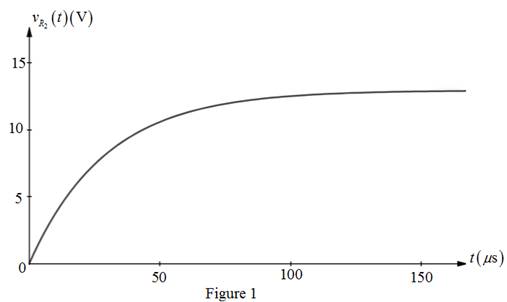
Fig. 11.84
Expert Solution & Answer
Want to see the full answer?
Check out a sample textbook solution
Students have asked these similar questions
25/
Identify the statement from the following when the inductance can have low value.
a.
If the number of turns of the wire is less
b.
If the cross-sectional area is lesser
c.
If the length of the wire is longer
d.
All the given options
4. An alternating voltage is represented by the expression v= 35 sin (314.2 t) volt. Determine,
i) the maximum value,
ii) the frequency,
iii) the period of the waveform, and
iv) the value 3.5 ms after it passes through zero, going positive.
(b) i. Explain the types of semiconductors and the classifications of the semiconductor materials.
ii. With the aid of a diagram, explain the formation of the P and N types of semiconductor.
For the network shown in figure (3), if the switch is closed for 2usec and then opened for Susec, find mathematical expressions for vi and in of both periods of time and then plot the waveforms of vL and i as a function of time.
Chapter 11 Solutions
Introductory Circuit Analysis (13th Edition)
Ch. 11 - For the electromagnet in Fig. 11.75: a. Find the...Ch. 11 - For the inductor in Fig. 11.76, find the...Ch. 11 - a. Repeat Problem 2 with a ferromagnetic core with...Ch. 11 - For the inductor in Fig. 11.77, find the...Ch. 11 - An air-core inductor has a total inductance of 4.7...Ch. 11 - What are the inductance and the range of expected...Ch. 11 - If the flux linking a coil of 50 turns changes at...Ch. 11 - Determine the rate of change of flux linking a...Ch. 11 - How many turns does a coil have if 42 mV are...Ch. 11 - Find the voltage induced across a coil of 22 mH if...
Ch. 11 - For the circuit of Fig. 11.78 composed of standard...Ch. 11 - For the circuit in Fig. 11.79 composed of standard...Ch. 11 - For the network of Fig. 11.80. a. Write the...Ch. 11 - Give a supply of 18 V, use standard values to...Ch. 11 - For the circuit in Fig. 11.82: a. Write the...Ch. 11 - In this problem, the effect of reversing the...Ch. 11 - For the network of Fig. 11.84: a. Find the...Ch. 11 - Prob. 18PCh. 11 - Prob. 19PCh. 11 - Prob. 20PCh. 11 - For the network in Fig. 11.88: a. Determine the...Ch. 11 - For the network in Fig. 11.89: a. Write the...Ch. 11 - Prob. 23PCh. 11 - For Fig. 11.91: a. Determine the mathematical...Ch. 11 - For Fig. 11.92: a. Determine the mathematical...Ch. 11 - For the network in Fig. 11.93, the switch is...Ch. 11 - The switch in Fig. 11.94 has been open for a long...Ch. 11 - Prob. 28PCh. 11 - The switch for the network in Fig. 11.96 has been...Ch. 11 - The switch in Fig. 11.97 has been closed for a...Ch. 11 - Given iL=100mA(1e-t/20ms) a. Determine iLatt=1ms....Ch. 11 - a. If the measured current for an inductor during...Ch. 11 - The network in Fig. 11.98 employs a DMM with an...Ch. 11 - Find the waveform for the voltage induced across a...Ch. 11 - Find the waveform for the voltage induced across a...Ch. 11 - Prob. 36PCh. 11 - Find the total inductance of the circuit of Fig....Ch. 11 - Find the total inductance for the network of Fig....Ch. 11 - Reduce the network in Fig. 11.104 to the fewest...Ch. 11 - Reduce the network in Fig. 11.105 to the fewest...Ch. 11 - Reduce the network of Fig. 11.106 to the fewest...Ch. 11 - For the network in Fig. 11.107: a. Write the...Ch. 11 - For the network in Fig. 11.108: a. Write the...Ch. 11 - For the network in Fig. 11.109. a. Find the...Ch. 11 - Find the steady-state currents I1 and I2 for the...Ch. 11 - Find the steady-state currents and voltages for...Ch. 11 - Find the steady-state currents and voltages for...Ch. 11 - Find the indicated steady-state currents and...Ch. 11 - Prob. 49PCh. 11 - Using PSpice or Multisim, verify the results of...Ch. 11 - Using the PSpice or Multisim, find the solution to...Ch. 11 - Using PSpice or Multisim, find the solution to...Ch. 11 - Using PSpice or Multisim, verify the results of...
Knowledge Booster


Learn more about
Need a deep-dive on the concept behind this application? Look no further. Learn more about this topic, electrical-engineering and related others by exploring similar questions and additional content below.Similar questions
- For the following circuit, do the following:a) Write the mathematical expressions for the voltage VC, VR1 and IC if the switch is on theposition 1.b) Find the voltage VC, VR1 and IC if the switch changes to a position 2 at t = 100ms.c) Determine the discharge time of the capacitor.d) Draw the charge and discharge waveforms.arrow_forwardSolve the following values in figure 1.0. Total Capacitance, Ct. Total Charge, Qt. Individual Charge of C1 Individual Charge of C2 Individual Charge of C3arrow_forwardlell L1 R Ro 2. In this figure, assume arbitrary numbers for R1, R2, L1, and L2 including some number for the battery E. Find the rate of current in which inductor one (L1) is changing just after the switch is closed. Next, find the current in L1 after some time after the switch has been closed. lellarrow_forward
- Linear voltammetry is so called because: The current changes linearly with the potential. temperature changes linearly with time The potential changes linearly with time. The current changes linearly with timearrow_forwardWhen the switch is in position 1, the circuit will charge the capacitor. Determine the equations for v(t) and i(t) for the charge phase and determine the voltage and current at time, t = 31 ms, in the charge phase.arrow_forwardA coil has a resistance of 18 when it mean temp is from 20o C to 50o C. Find its mean temp rise when its resistance is 21 and the surrounding temp is 15o C. A potential difference of 250 V is applied to a copper field coil at a temp of 15o C and the current is 5A. What will be the mean temp of the coil when the current has fallen to 3.91 A, the applied voltage being the same as before.arrow_forward
- Determine the values of resistance R and inductance Larrow_forwardQ3] Design a circuit to produce an average voltage of 27V across a 102 load resistor from a 70V rms 50-Hz ac source. Verify your answer by the following: a) Draw the circuit. b) Draw to scale the waveforms for the input, output voltages and the current.arrow_forwardDetermine the current Ic, current at the resistor, and current supplied by the voltage source. Note: you must put the imaginary part of the reactances and its signarrow_forward
- Please write the solution clearlyarrow_forward11:03 b C Pmark question If the forward voltage drop on a diode is 774 mV, what is the current passing through it? Assume I s =3,4x10⁻¹⁶ A. If the forward voltage drop across a diode is 774 mV, what is the current flowing through it? Is =3.4x10 Get an A. -16 ( a. 2,885 mA b. 4,327 mA c. 3,606 mA D. 2,163 mA O to. 5,048 mA { * . . 51% - Previous page ||| Next page ← Announcements - Teams code: fmf9zv7 <arrow_forward1. Differentiate DC and AC voltage sources in terms of a) value of voltage, b) direction of current produced, and c) waveform or graph of value versus time. Based on the graph in no.1a), express the capacitor voltage after one time constant, in terms of the charging voltage. Based on the graph in no.1b), express the capacitor voltage after one time constant, in terms of the initial voltagearrow_forward
arrow_back_ios
SEE MORE QUESTIONS
arrow_forward_ios
Recommended textbooks for you
 Introductory Circuit Analysis (13th Edition)Electrical EngineeringISBN:9780133923605Author:Robert L. BoylestadPublisher:PEARSON
 Delmar's Standard Textbook Of ElectricityElectrical EngineeringISBN:9781337900348Author:Stephen L. HermanPublisher:Cengage Learning
 Programmable Logic ControllersElectrical EngineeringISBN:9780073373843Author:Frank D. PetruzellaPublisher:McGraw-Hill Education
 Fundamentals of Electric CircuitsElectrical EngineeringISBN:9780078028229Author:Charles K Alexander, Matthew SadikuPublisher:McGraw-Hill Education
 Electric Circuits. (11th Edition)Electrical EngineeringISBN:9780134746968Author:James W. Nilsson, Susan RiedelPublisher:PEARSON
 Engineering ElectromagneticsElectrical EngineeringISBN:9780078028151Author:Hayt, William H. (william Hart), Jr, BUCK, John A.Publisher:Mcgraw-hill Education,
Introductory Circuit Analysis (13th Edition)
Electrical Engineering
ISBN:9780133923605
Author:Robert L. Boylestad
Publisher:PEARSON
Delmar's Standard Textbook Of Electricity
Electrical Engineering
ISBN:9781337900348
Author:Stephen L. Herman
Publisher:Cengage Learning
Programmable Logic Controllers
Electrical Engineering
ISBN:9780073373843
Author:Frank D. Petruzella
Publisher:McGraw-Hill Education
Fundamentals of Electric Circuits
Electrical Engineering
ISBN:9780078028229
Author:Charles K Alexander, Matthew Sadiku
Publisher:McGraw-Hill Education
Electric Circuits. (11th Edition)
Electrical Engineering
ISBN:9780134746968
Author:James W. Nilsson, Susan Riedel
Publisher:PEARSON
Engineering Electromagnetics
Electrical Engineering
ISBN:9780078028151
Author:Hayt, William H. (william Hart), Jr, BUCK, John A.
Publisher:Mcgraw-hill Education,
Inductors Explained - The basics how inductors work working principle; Author: The Engineering Mindset;https://www.youtube.com/watch?v=KSylo01n5FY;License: Standard Youtube License