
Introductory Circuit Analysis (13th Edition)
13th Edition
ISBN: 9780133923605
Author: Robert L. Boylestad
Publisher: PEARSON
expand_more
expand_more
format_list_bulleted
Videos
Textbook Question
Chapter 11, Problem 16P
In this problem, the effect of reversing the initial current is investigated. The circuit in Fig.
11.83 is the same as that appearing in Fig. 11.82, with the only change being the direction of the initial current.
a. Write the mathematical expressions for the current iL and the voltage vL following the closing of the switch. Take careful note of the defined polarity for vL and the direction for iL
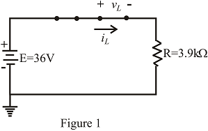
Fig. 11.83
b. Sketch the waveform of iL and vL for the entire penod from initial value to steady-state level.
c. Compare the results with those of Problem 15.
Expert Solution & Answer

Trending nowThis is a popular solution!

Students have asked these similar questions
Alternating voltage and current differ from
direct voltage and current because alternating
voltage and current
a.)never change.
b.)change polarity.
c.)maintain a constant polarity.
d.)are not real electricity
The period (T) of a waveform is
a.)unrelated to the frequency.
b.) the reciprocal of the frequency.
c.)equal to the frequency.
d.)the reciprocal of the cycle
An e.m.f. of 16 volts is induced in a coil of inductance 4H. The rate of change of current
must be
(a) 64 A/s
(b) 32 A/s
(c) 16 A/s
(d) 4 A/s
Q13) For the circuit shown in the figure.
a) Calculate the ripple factor.
b) Sketch and label the output voltage waveform .
T1
D1
V1
120Vpk
60HZ
0°
10:1
C1
1G4B42
R1
:100μΕ
1.5kQ
014) Sketch th
I the touol
Chapter 11 Solutions
Introductory Circuit Analysis (13th Edition)
Ch. 11 - For the electromagnet in Fig. 11.75: a. Find the...Ch. 11 - For the inductor in Fig. 11.76, find the...Ch. 11 - a. Repeat Problem 2 with a ferromagnetic core with...Ch. 11 - For the inductor in Fig. 11.77, find the...Ch. 11 - An air-core inductor has a total inductance of 4.7...Ch. 11 - What are the inductance and the range of expected...Ch. 11 - If the flux linking a coil of 50 turns changes at...Ch. 11 - Determine the rate of change of flux linking a...Ch. 11 - How many turns does a coil have if 42 mV are...Ch. 11 - Find the voltage induced across a coil of 22 mH if...
Ch. 11 - For the circuit of Fig. 11.78 composed of standard...Ch. 11 - For the circuit in Fig. 11.79 composed of standard...Ch. 11 - For the network of Fig. 11.80. a. Write the...Ch. 11 - Give a supply of 18 V, use standard values to...Ch. 11 - For the circuit in Fig. 11.82: a. Write the...Ch. 11 - In this problem, the effect of reversing the...Ch. 11 - For the network of Fig. 11.84: a. Find the...Ch. 11 - Prob. 18PCh. 11 - Prob. 19PCh. 11 - Prob. 20PCh. 11 - For the network in Fig. 11.88: a. Determine the...Ch. 11 - For the network in Fig. 11.89: a. Write the...Ch. 11 - Prob. 23PCh. 11 - For Fig. 11.91: a. Determine the mathematical...Ch. 11 - For Fig. 11.92: a. Determine the mathematical...Ch. 11 - For the network in Fig. 11.93, the switch is...Ch. 11 - The switch in Fig. 11.94 has been open for a long...Ch. 11 - Prob. 28PCh. 11 - The switch for the network in Fig. 11.96 has been...Ch. 11 - The switch in Fig. 11.97 has been closed for a...Ch. 11 - Given iL=100mA(1e-t/20ms) a. Determine iLatt=1ms....Ch. 11 - a. If the measured current for an inductor during...Ch. 11 - The network in Fig. 11.98 employs a DMM with an...Ch. 11 - Find the waveform for the voltage induced across a...Ch. 11 - Find the waveform for the voltage induced across a...Ch. 11 - Prob. 36PCh. 11 - Find the total inductance of the circuit of Fig....Ch. 11 - Find the total inductance for the network of Fig....Ch. 11 - Reduce the network in Fig. 11.104 to the fewest...Ch. 11 - Reduce the network in Fig. 11.105 to the fewest...Ch. 11 - Reduce the network of Fig. 11.106 to the fewest...Ch. 11 - For the network in Fig. 11.107: a. Write the...Ch. 11 - For the network in Fig. 11.108: a. Write the...Ch. 11 - For the network in Fig. 11.109. a. Find the...Ch. 11 - Find the steady-state currents I1 and I2 for the...Ch. 11 - Find the steady-state currents and voltages for...Ch. 11 - Find the steady-state currents and voltages for...Ch. 11 - Find the indicated steady-state currents and...Ch. 11 - Prob. 49PCh. 11 - Using PSpice or Multisim, verify the results of...Ch. 11 - Using the PSpice or Multisim, find the solution to...Ch. 11 - Using PSpice or Multisim, find the solution to...Ch. 11 - Using PSpice or Multisim, verify the results of...
Knowledge Booster


Learn more about
Need a deep-dive on the concept behind this application? Look no further. Learn more about this topic, electrical-engineering and related others by exploring similar questions and additional content below.Similar questions
- A triangle waveform with following specifications in Table B1. Table B1 RMS Voltage 50mV Number of cycles/second 100 i) Sketch the approximate triangular waveform with all specifications. ii) A transformer has primary coil with 100 turns and secondary coil with 120 turns. Estimate the current in the secondary coil, If the current in the primary coil is 4 Amperearrow_forward... 0.25 A 120 V 60 Hz RL 1 k2 470 µF When the circuit is working normally, it has an rms secondary voltage of 12.49 volts. Considering the ripple voltage, what is thnimum dc load voltage?arrow_forwardQUESTION 11 An inductor is connected in parallel with a 6540 resistor and a function generator. The applied voltage is 42V RMS and the total current is 67mA RMS. Find the magnitude of the current through the inductor. Enter your answer in the space provided. Round your answer to one decimal place. Your answer should be in mA but do not enter the unit.arrow_forward
- 1. The average (DC) value of a half-wave rectified voltage with a peak value of 200 V is: a. 63.7 V b. 127.3 V c. 141 V d. OV 2. Voltage regulation is determined byarrow_forward... 0.25 A 120 V 60 Hz RL 1 k2 470 μ When the circuit is working normally, it has an rms secondary voltage of 11.91 volts. What is the peak-to-peak ripple voltage?arrow_forwardWhat is the common frequency of alternating current in the United States? Select one: A. 25 HERTZ B. 50 HERTZ C. 60 HERTZ D. NONE OF THE ABOVEarrow_forward
- What are the things common in direct current and alternating current. And also its Differencearrow_forwardAn e.m.f of 30 volts is induced in a coil of inductance 60 H, then the rate of change of current is O 5 A/sec o 50 A/sec O 0.5 A/sec o 500 A/secarrow_forward8. Liquids with solid impurities a) Have higher dielectric strength b) Of large size have higher dielectric strength c) Have lower dielectric strength as compared to pure liquids d) None of the above 9. Peak to peak ripple is defined as a) the difference between average de voltage and peak value b) the difference between maximum and minimum de voltage c) the difference between maximum ac and average de voltages d) the difference between ac (rms) and average de voltages 10. In a Cockroft-Walton circuit, input voltage 100 kV load current 25 mA, supply frequency 100 Hz, each capacitor 10 nF. The optimum no. of stages for maximum output voltage is a) 1 b) 2 c) 10 d) 35arrow_forward
- 5/1 IN4001 120 V 60 Hz R 5 k2 100 uF 1) Explain how this circuit works 2) Draw the waveform at the output (Vrl) for a sinusoidal signal at the input 3) What is the effective voltage of peak voltage in the secondary? 4) What is the peak voltage on the load? 5) What is the average voltage of the output (on the load)? 6) Calculate ripple on loadarrow_forwardDetermine the maximum peak-to-peak ripple current of previous problem by using the next equations, and compare the results. DI. = max V R tanh R 4fL DI = V S max 4fLarrow_forwardFor the cycle circuit, when will the PIV appear when the input waveform will occur? Please choose one: a. B b. One c. C Darrow_forward
arrow_back_ios
SEE MORE QUESTIONS
arrow_forward_ios
Recommended textbooks for you
 Delmar's Standard Textbook Of ElectricityElectrical EngineeringISBN:9781337900348Author:Stephen L. HermanPublisher:Cengage Learning
 Electricity for Refrigeration, Heating, and Air C...Mechanical EngineeringISBN:9781337399128Author:Russell E. SmithPublisher:Cengage Learning
Delmar's Standard Textbook Of Electricity
Electrical Engineering
ISBN:9781337900348
Author:Stephen L. Herman
Publisher:Cengage Learning
Electricity for Refrigeration, Heating, and Air C...
Mechanical Engineering
ISBN:9781337399128
Author:Russell E. Smith
Publisher:Cengage Learning
How do Universal Motors work ?; Author: Lesics;https://www.youtube.com/watch?v=0PDRJKz-mqE;License: Standard Youtube License