
Introductory Circuit Analysis (13th Edition)
13th Edition
ISBN: 9780133923605
Author: Robert L. Boylestad
Publisher: PEARSON
expand_more
expand_more
format_list_bulleted
Videos
Textbook Question
Chapter 11, Problem 26P
For the network in Fig. 11.93, the switch is closed at
a. Determine vL at
b. Find vL at
c. Calculate vR1 at
d. Find the time required for the current iL to reach 1 mA.
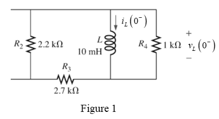
Fig. 11.93
Expert Solution & Answer
Want to see the full answer?
Check out a sample textbook solution
Students have asked these similar questions
A capacitor drawing 4 kvar is placed in parallel with the electro-magnet that draws 3 kW of active power and 4 kvar of reactive power.. a. Calculate the new value of apparent power b. What is the new value of reactive power? c. What is the value of active power? d. What is the new power factor?
TOPIC: Fundamentals of Alternating Current Powers
Give illustration and a step by step solution. Final answer must be in 4 decimal places.
1. A load takes 55kW at 70% power factor lagging from a 240V, 50Hz supply. If the supply is made 60Hz, with the voltage remaining the same, what will be the kW load at 60Hz?
2. An inductive coil takes a current of 2A and consumes 160W when connected to a 240V supply. A second coil when connected across the same supply takes 3A and 500W. Find the total power when the two coils are connected in series to the supply.
3. A series RC circuit is connected to 230V, 60Hz source. If the power taken by the circuit is 4,800W and the voltage drop across the resistor is 115V, calculate the capacitance of the
capacitor.
Thank You in advance!
For the circuit in fig .11.82
A. Write the mathematical expressions for the current IL and the voltage Vl following the closing of the switch.
B. Sketch the waveform of iL and VL for the entire period from initial value to steady-state level.
Chapter 11 Solutions
Introductory Circuit Analysis (13th Edition)
Ch. 11 - For the electromagnet in Fig. 11.75: a. Find the...Ch. 11 - For the inductor in Fig. 11.76, find the...Ch. 11 - a. Repeat Problem 2 with a ferromagnetic core with...Ch. 11 - For the inductor in Fig. 11.77, find the...Ch. 11 - An air-core inductor has a total inductance of 4.7...Ch. 11 - What are the inductance and the range of expected...Ch. 11 - If the flux linking a coil of 50 turns changes at...Ch. 11 - Determine the rate of change of flux linking a...Ch. 11 - How many turns does a coil have if 42 mV are...Ch. 11 - Find the voltage induced across a coil of 22 mH if...
Ch. 11 - For the circuit of Fig. 11.78 composed of standard...Ch. 11 - For the circuit in Fig. 11.79 composed of standard...Ch. 11 - For the network of Fig. 11.80. a. Write the...Ch. 11 - Give a supply of 18 V, use standard values to...Ch. 11 - For the circuit in Fig. 11.82: a. Write the...Ch. 11 - In this problem, the effect of reversing the...Ch. 11 - For the network of Fig. 11.84: a. Find the...Ch. 11 - Prob. 18PCh. 11 - Prob. 19PCh. 11 - Prob. 20PCh. 11 - For the network in Fig. 11.88: a. Determine the...Ch. 11 - For the network in Fig. 11.89: a. Write the...Ch. 11 - Prob. 23PCh. 11 - For Fig. 11.91: a. Determine the mathematical...Ch. 11 - For Fig. 11.92: a. Determine the mathematical...Ch. 11 - For the network in Fig. 11.93, the switch is...Ch. 11 - The switch in Fig. 11.94 has been open for a long...Ch. 11 - Prob. 28PCh. 11 - The switch for the network in Fig. 11.96 has been...Ch. 11 - The switch in Fig. 11.97 has been closed for a...Ch. 11 - Given iL=100mA(1e-t/20ms) a. Determine iLatt=1ms....Ch. 11 - a. If the measured current for an inductor during...Ch. 11 - The network in Fig. 11.98 employs a DMM with an...Ch. 11 - Find the waveform for the voltage induced across a...Ch. 11 - Find the waveform for the voltage induced across a...Ch. 11 - Prob. 36PCh. 11 - Find the total inductance of the circuit of Fig....Ch. 11 - Find the total inductance for the network of Fig....Ch. 11 - Reduce the network in Fig. 11.104 to the fewest...Ch. 11 - Reduce the network in Fig. 11.105 to the fewest...Ch. 11 - Reduce the network of Fig. 11.106 to the fewest...Ch. 11 - For the network in Fig. 11.107: a. Write the...Ch. 11 - For the network in Fig. 11.108: a. Write the...Ch. 11 - For the network in Fig. 11.109. a. Find the...Ch. 11 - Find the steady-state currents I1 and I2 for the...Ch. 11 - Find the steady-state currents and voltages for...Ch. 11 - Find the steady-state currents and voltages for...Ch. 11 - Find the indicated steady-state currents and...Ch. 11 - Prob. 49PCh. 11 - Using PSpice or Multisim, verify the results of...Ch. 11 - Using the PSpice or Multisim, find the solution to...Ch. 11 - Using PSpice or Multisim, find the solution to...Ch. 11 - Using PSpice or Multisim, verify the results of...
Knowledge Booster


Learn more about
Need a deep-dive on the concept behind this application? Look no further. Learn more about this topic, electrical-engineering and related others by exploring similar questions and additional content below.Similar questions
- 22 1852 172 12 52 The circuit shown in Figure has been connected for a long time. What is the potential difference across the 22-2 resistor? O A) 13.5 V O B) 32.4 V C) 72 V O D) 58.5 V E) 39.6 Varrow_forwardIt states that "in any electrical network, the algebraic sum of the currents meeting at a point or junction is zero". a. kirchoff's current law b. kircchoff's current law c. kirchooff's current law d. kirchhoff's current lawarrow_forwardPlease answer a, b, c, d in Q3. Thanks! Q1. An electro-magnet draws 3 kW of active power and 3 kvar of reactive power. Q2. A capacitor drawing 4 kvar is placed in parallel with the electro-magnet of Q1. Q3. If the capacitor of Q2 is replaced with one drawing 8 kvar, calculate: A. The new value of apparent power B. The new reactive power C. The new active power D. The new power factorarrow_forward
- 11. Two coupled coils have self-inductances L1 = 2 Hand L2 = 0.5 H, and a coefficient of coupling K = 0.9. Determine the turns ratio N1/N2 of the two coils. ww w а. 2 b. 0.2 c. 0.5 d. 0.9arrow_forwardThermal power plants classified according to prime mover and has the highest efficiency is the combined cycle. Select one: O True O False Next page cage O Power system General (Power Sys. earcharrow_forwardReactance is:A) measured in Ohms B) affected by frequency of the power supply C) Both of the aboveD) None of the abovearrow_forward
- 13. Which of the following quantity is/ are change in substations? a) Voltage b) AC to DC c) Frequency d) all of the above 3 17 8 10 11 12 6arrow_forwardA steam turbine generator is designed to generate 5.5MW of electrical power at a 6300V, 50HZ and 0.95 lag. The steam turbine requires 28 tons per hour of a high-pressure steam of temperature and pressure of 4000C and 40 bar. The steam turbine is a condensing type. If the temperature of the exhaust steam is 400 C (a).Calculate the efficiency of the steam turbine (b)What are the three (3) major advantages and disadvantages of the steam turbine? (c )What are the methods of improving efficiency of the Brayton cycle?arrow_forward1. A coil of 2000 turns with a 100-mA current has a length of 0.2 m. (a) Calculate H in ampere-turns per the mmf in ampere-turns. (b) Calculate the field intensity meter.arrow_forward
- in a work environment 50 Hz 220V Find the following hardware in the power system 1.. .piece 100W incandescent filament lamp 2.power.. .kW efficient %88 power factor 0.85 asynchronous motor with 3.power 2000W a heater with power factor of the power system. .Calculate the capacity of the capacitor that needs to be added to the circuit in order to determine the places to be written in the blankarrow_forwardFundamentals of Electrical Engineering 2020/2021 na ea Dr. Yaseen H. Tahir Example: Find the voltage Vo in the circuit in Figure belownin 2 kn 3 kN 41, Vs 10 mA 4 k2 Solution: wongs.senlo vleoleyy son bas s) 2 llaw es (s be ) amioq soni2 Jutoeu o ei noitsion A vlgne Jaum ow aglowondnu or gniniomotob of obno nl getlov oln adi to teianoo isdi disq boeolo oniolab otanolenadT e ul deq sdl ou n ov ( anielsb o ba 1 b we 62 g s 1o darrow_forwardKindly answer a,b,c,d. Thanks! Q1. An electro-magnet draws 3 kW of active power and 4 kvar of reactive power Q2. A capacitor drawing 4 kvar is placed in parallel with the electro-magnet of Q1. a.) calculate the new value of apparent power b.) what is the new value of reactive power c.) what is the new value of active power d.) what is the new power factorarrow_forward
arrow_back_ios
SEE MORE QUESTIONS
arrow_forward_ios
Recommended textbooks for you

How do Universal Motors work ?; Author: Lesics;https://www.youtube.com/watch?v=0PDRJKz-mqE;License: Standard Youtube License