
Introductory Circuit Analysis (13th Edition)
13th Edition
ISBN: 9780133923605
Author: Robert L. Boylestad
Publisher: PEARSON
expand_more
expand_more
format_list_bulleted
Videos
Textbook Question
Chapter 11, Problem 27P
The switch in Fig. 11.94 has been open for a long time. It is then closed at
a. Write the mathematical expression for the current iL and the voltage vL after the switch is closed.
b. Sketch the waveform of iL and vL from the initial value to the steady-state level.
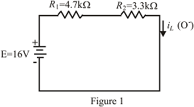
Fig. 11.94
Expert Solution & Answer
Want to see the full answer?
Check out a sample textbook solution
Students have asked these similar questions
For the circuit below assuming an ideal switch, preform transient analysis to predict the voltage
across resistor, R2 and plot the results. The inductor will have zero current as initial condition.
L1
0.005
2
U1
100mH
R1
1k
V1
20Vdc
R2
100
Q52. How much energy is stored by a 100 m H inductance
with a current of 1 A?
A. 100 J
B. 1 J
C. 0.05 J
D. 0.01 J
1. What impedance vector 0 – j22 represents:A. A pure resistance.B. A pure inductance.C. A pure capacitance.D. An inductance combined with a resistance.
Chapter 11 Solutions
Introductory Circuit Analysis (13th Edition)
Ch. 11 - For the electromagnet in Fig. 11.75: a. Find the...Ch. 11 - For the inductor in Fig. 11.76, find the...Ch. 11 - a. Repeat Problem 2 with a ferromagnetic core with...Ch. 11 - For the inductor in Fig. 11.77, find the...Ch. 11 - An air-core inductor has a total inductance of 4.7...Ch. 11 - What are the inductance and the range of expected...Ch. 11 - If the flux linking a coil of 50 turns changes at...Ch. 11 - Determine the rate of change of flux linking a...Ch. 11 - How many turns does a coil have if 42 mV are...Ch. 11 - Find the voltage induced across a coil of 22 mH if...
Ch. 11 - For the circuit of Fig. 11.78 composed of standard...Ch. 11 - For the circuit in Fig. 11.79 composed of standard...Ch. 11 - For the network of Fig. 11.80. a. Write the...Ch. 11 - Give a supply of 18 V, use standard values to...Ch. 11 - For the circuit in Fig. 11.82: a. Write the...Ch. 11 - In this problem, the effect of reversing the...Ch. 11 - For the network of Fig. 11.84: a. Find the...Ch. 11 - Prob. 18PCh. 11 - Prob. 19PCh. 11 - Prob. 20PCh. 11 - For the network in Fig. 11.88: a. Determine the...Ch. 11 - For the network in Fig. 11.89: a. Write the...Ch. 11 - Prob. 23PCh. 11 - For Fig. 11.91: a. Determine the mathematical...Ch. 11 - For Fig. 11.92: a. Determine the mathematical...Ch. 11 - For the network in Fig. 11.93, the switch is...Ch. 11 - The switch in Fig. 11.94 has been open for a long...Ch. 11 - Prob. 28PCh. 11 - The switch for the network in Fig. 11.96 has been...Ch. 11 - The switch in Fig. 11.97 has been closed for a...Ch. 11 - Given iL=100mA(1e-t/20ms) a. Determine iLatt=1ms....Ch. 11 - a. If the measured current for an inductor during...Ch. 11 - The network in Fig. 11.98 employs a DMM with an...Ch. 11 - Find the waveform for the voltage induced across a...Ch. 11 - Find the waveform for the voltage induced across a...Ch. 11 - Prob. 36PCh. 11 - Find the total inductance of the circuit of Fig....Ch. 11 - Find the total inductance for the network of Fig....Ch. 11 - Reduce the network in Fig. 11.104 to the fewest...Ch. 11 - Reduce the network in Fig. 11.105 to the fewest...Ch. 11 - Reduce the network of Fig. 11.106 to the fewest...Ch. 11 - For the network in Fig. 11.107: a. Write the...Ch. 11 - For the network in Fig. 11.108: a. Write the...Ch. 11 - For the network in Fig. 11.109. a. Find the...Ch. 11 - Find the steady-state currents I1 and I2 for the...Ch. 11 - Find the steady-state currents and voltages for...Ch. 11 - Find the steady-state currents and voltages for...Ch. 11 - Find the indicated steady-state currents and...Ch. 11 - Prob. 49PCh. 11 - Using PSpice or Multisim, verify the results of...Ch. 11 - Using the PSpice or Multisim, find the solution to...Ch. 11 - Using PSpice or Multisim, find the solution to...Ch. 11 - Using PSpice or Multisim, verify the results of...
Knowledge Booster


Learn more about
Need a deep-dive on the concept behind this application? Look no further. Learn more about this topic, electrical-engineering and related others by exploring similar questions and additional content below.Similar questions
- capacitor having capacitance of 10uF is connected with 1k ohm resistor in series. The switch of the DC supply of 10 Volts, closes at t = 0. Compute the following a. Draw a circuit diagram for t- and t+ b. Compute the time constant c. Plot the Voltage with respect to time, showing the behavior of capacitor charging(take at least 10 values of time in seconds to draw a graph).arrow_forwardDraw the inductance and resistance voltages on an oscilloscope screen in accordance with their polarity. In the drawing, it should start with voltage changes and values and should be stable. Write the Time/Div and Volt/Div steps made on the oscilloscope during the measurement on the oscilloscope screen drawing. Specify the voltage labels in the drawing. The current through the circuit has the same variation as the resistor voltage measured from the equation V=I/R, but is 1/47 times the value.arrow_forwardWhat is the value of the induced voltage of the self-inductance when the rate of current is from 200 uA to 20 uA and the total time interval is 5 uS?arrow_forward
- Q21(i) In an AC Circuit, the peak value of current is 7 A and its frequency is 125 Hz. Estimate the time taken by the current to reach its maximum value after from starting from zero.arrow_forwardPlease express the two signals as sine functions. Therefore, find the respective parameters and use the current as reference.arrow_forwardFor the network shown in figure (3), if the switch is closed for 2usec and then opened for Susec, find mathematical expressions for vi and in of both periods of time and then plot the waveforms of vL and i as a function of time.arrow_forward
- Show all work please and thank you :)arrow_forwardAC 15. What would the equivalent resistance be of a 159 uF capacitor? 16. What is the RMS voltage of a circuit if the peak voltage is 170 volts? 17. If the RMS voltage is 240 volts AC, what is the peak voltage? 18. What is the formula for finding an inductors equivalent resistance? 19. What is the equivalent resistance of an inductor with 0.17 henrys? 20. What is the symbol of an AC power source? 21. What is the equivalent inductance of a parallel circuit with a 0.01L, 0.02L, and 1.7L inductor? 22. What is the equivalent inductance of a series circuit with a 0.03L, 0.04L, and 1.6L inductor? 23. A transformer with a primary voltage of 480 volts and a turns ratio of 2:1 will have what secondary voltage? 24. A Power Network is comprised of what three components? 25. What is the main difference between a fuse and a circuit breaker?arrow_forwardCalculate Fermi Function in the following scenarios: Energy level at positive infinityarrow_forward
- The diagram shows an inductor that is part of a circuit. The direction of the emf induced in the inductor is indicated. Which of the following is possible? elle O a. The current is increasing and leftward O b. The current is constant and leftward. O c. None of these. O d. The current is increasing and rightward. O e. The current is constant and rightward.arrow_forwardIf the input voltage for the given circuit below is 220 V at 50 Hz, the load resistance (RL) is 3300 and the average output voltage is 20 V. Assume the diodes to be germanium diodes. Determine the turns ratio of the transformer used. If a capacitor of 100 µF is connected parallel to the load resistor (RL), Determine the ripple factor. D1 D2 V D3 .... D4 RL a. The turns ratio of transformer (Npri/Nsec) is b. The Ripple factor is cell rellarrow_forwardIf the input voltage for the given circuit below is 220 V at 60 Hz, the load resistance (RL) is 3302 and the average output voltage is 20 V. Assume the diodes to be silicon diodes. Determine the turns ratio of the transformer used. If a capacitor of 100 µF is connected parallel to the load resistor (RL), Determine the ripple factor. D3 D1 V + RL D2 D4 a. The turns ratio of transformer (Npri/Nsec) is b. The Ripple factor is illlarrow_forward
arrow_back_ios
SEE MORE QUESTIONS
arrow_forward_ios
Recommended textbooks for you
 Introductory Circuit Analysis (13th Edition)Electrical EngineeringISBN:9780133923605Author:Robert L. BoylestadPublisher:PEARSON
 Delmar's Standard Textbook Of ElectricityElectrical EngineeringISBN:9781337900348Author:Stephen L. HermanPublisher:Cengage Learning
 Programmable Logic ControllersElectrical EngineeringISBN:9780073373843Author:Frank D. PetruzellaPublisher:McGraw-Hill Education
 Fundamentals of Electric CircuitsElectrical EngineeringISBN:9780078028229Author:Charles K Alexander, Matthew SadikuPublisher:McGraw-Hill Education
 Electric Circuits. (11th Edition)Electrical EngineeringISBN:9780134746968Author:James W. Nilsson, Susan RiedelPublisher:PEARSON
 Engineering ElectromagneticsElectrical EngineeringISBN:9780078028151Author:Hayt, William H. (william Hart), Jr, BUCK, John A.Publisher:Mcgraw-hill Education,
Introductory Circuit Analysis (13th Edition)
Electrical Engineering
ISBN:9780133923605
Author:Robert L. Boylestad
Publisher:PEARSON
Delmar's Standard Textbook Of Electricity
Electrical Engineering
ISBN:9781337900348
Author:Stephen L. Herman
Publisher:Cengage Learning
Programmable Logic Controllers
Electrical Engineering
ISBN:9780073373843
Author:Frank D. Petruzella
Publisher:McGraw-Hill Education
Fundamentals of Electric Circuits
Electrical Engineering
ISBN:9780078028229
Author:Charles K Alexander, Matthew Sadiku
Publisher:McGraw-Hill Education
Electric Circuits. (11th Edition)
Electrical Engineering
ISBN:9780134746968
Author:James W. Nilsson, Susan Riedel
Publisher:PEARSON
Engineering Electromagnetics
Electrical Engineering
ISBN:9780078028151
Author:Hayt, William H. (william Hart), Jr, BUCK, John A.
Publisher:Mcgraw-hill Education,
ECE320 Lecture1-3c: Steady-State Error, System Type; Author: Rose-Hulman Online;https://www.youtube.com/watch?v=hG7dq-51AAg;License: Standard Youtube License