
Introductory Circuit Analysis (13th Edition)
13th Edition
ISBN: 9780133923605
Author: Robert L. Boylestad
Publisher: PEARSON
expand_more
expand_more
format_list_bulleted
Videos
Textbook Question
Chapter 11, Problem 12P
For the circuit in Fig. 11.79 composed of standard values:
a. Determine T
b. Write the mathematical expression for the current iL after the switch is closed at
c. Write the mathematical expression for VL and VR after the switch is closed at
d. Determine iL and VL at
e. Sketch the waveforms of iL, vL. and VR for the storage phase.
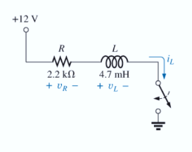
Fig. 11.79
Expert Solution & Answer
Want to see the full answer?
Check out a sample textbook solution
Students have asked these similar questions
Q21(i) In an AC Circuit, the peak value of current is 7 A and its frequency is 125 Hz. Estimate
the time taken by the current to reach its maximum value after from starting from zero.
Question 4
Figure 7 shows a recorded current waveform i(@t) from a
converter. The current is related to (@t) during each cycle and
alternates between 0 and +IL. The current waveform varies with
time at constant frequency.
i(ot
+IL
ot
-T
-Tt/2
T/2
3t/2
Figure 7
a) Determine the expression that describes the waveform i(@t)
shown in Figure 7 as a function of ot.
1
b) Calculate the average value: a, .
c) Identify all symmetries of the waveform i(ot)
Figure 7.
15 Kh
30v
d. How many tíme constants will it take for te
voltage to reach 23 v?
C. Gweng that the capacitor is fully charged, how
long will it take por it to be `20% ?
120v
8F
what is the t?'
b. what is the voltage capactor apter 10 sec?
a.
C. How many time constants will it take for tue
Vo itage to reach 80 v.?
d. Given that the capaator is Fully charged, how
time constants will it be to reau
many
GOV!
Chapter 11 Solutions
Introductory Circuit Analysis (13th Edition)
Ch. 11 - For the electromagnet in Fig. 11.75: a. Find the...Ch. 11 - For the inductor in Fig. 11.76, find the...Ch. 11 - a. Repeat Problem 2 with a ferromagnetic core with...Ch. 11 - For the inductor in Fig. 11.77, find the...Ch. 11 - An air-core inductor has a total inductance of 4.7...Ch. 11 - What are the inductance and the range of expected...Ch. 11 - If the flux linking a coil of 50 turns changes at...Ch. 11 - Determine the rate of change of flux linking a...Ch. 11 - How many turns does a coil have if 42 mV are...Ch. 11 - Find the voltage induced across a coil of 22 mH if...
Ch. 11 - For the circuit of Fig. 11.78 composed of standard...Ch. 11 - For the circuit in Fig. 11.79 composed of standard...Ch. 11 - For the network of Fig. 11.80. a. Write the...Ch. 11 - Give a supply of 18 V, use standard values to...Ch. 11 - For the circuit in Fig. 11.82: a. Write the...Ch. 11 - In this problem, the effect of reversing the...Ch. 11 - For the network of Fig. 11.84: a. Find the...Ch. 11 - Prob. 18PCh. 11 - Prob. 19PCh. 11 - Prob. 20PCh. 11 - For the network in Fig. 11.88: a. Determine the...Ch. 11 - For the network in Fig. 11.89: a. Write the...Ch. 11 - Prob. 23PCh. 11 - For Fig. 11.91: a. Determine the mathematical...Ch. 11 - For Fig. 11.92: a. Determine the mathematical...Ch. 11 - For the network in Fig. 11.93, the switch is...Ch. 11 - The switch in Fig. 11.94 has been open for a long...Ch. 11 - Prob. 28PCh. 11 - The switch for the network in Fig. 11.96 has been...Ch. 11 - The switch in Fig. 11.97 has been closed for a...Ch. 11 - Given iL=100mA(1e-t/20ms) a. Determine iLatt=1ms....Ch. 11 - a. If the measured current for an inductor during...Ch. 11 - The network in Fig. 11.98 employs a DMM with an...Ch. 11 - Find the waveform for the voltage induced across a...Ch. 11 - Find the waveform for the voltage induced across a...Ch. 11 - Prob. 36PCh. 11 - Find the total inductance of the circuit of Fig....Ch. 11 - Find the total inductance for the network of Fig....Ch. 11 - Reduce the network in Fig. 11.104 to the fewest...Ch. 11 - Reduce the network in Fig. 11.105 to the fewest...Ch. 11 - Reduce the network of Fig. 11.106 to the fewest...Ch. 11 - For the network in Fig. 11.107: a. Write the...Ch. 11 - For the network in Fig. 11.108: a. Write the...Ch. 11 - For the network in Fig. 11.109. a. Find the...Ch. 11 - Find the steady-state currents I1 and I2 for the...Ch. 11 - Find the steady-state currents and voltages for...Ch. 11 - Find the steady-state currents and voltages for...Ch. 11 - Find the indicated steady-state currents and...Ch. 11 - Prob. 49PCh. 11 - Using PSpice or Multisim, verify the results of...Ch. 11 - Using the PSpice or Multisim, find the solution to...Ch. 11 - Using PSpice or Multisim, find the solution to...Ch. 11 - Using PSpice or Multisim, verify the results of...
Knowledge Booster


Learn more about
Need a deep-dive on the concept behind this application? Look no further. Learn more about this topic, electrical-engineering and related others by exploring similar questions and additional content below.Similar questions
- The peak time for the first overshoot in the figure is : C(t) 1. 28 1 step input 3 secarrow_forwardA 70-Vac source has the following waveform.Determine:a. the instantaneous voltage when t = 120 msb. the angle (1st occurrence) after t = 0 when the voltage is +80 Vc. the time (2nd occurrence) after t = 0 when the voltage is –10 Varrow_forwardIf the input voltage for the given circuit below is 220 V at 60 Hz, the load resistance (RL) is 3302 and the average output voltage is 20 V. Assume the diodes to be silicon diodes. Determine the turns ratio of the transformer used. If a capacitor of 100 µF is connected parallel to the load resistor (RL), Determine the ripple factor. D3 D1 V + RL D2 D4 a. The turns ratio of transformer (Npri/Nsec) is b. The Ripple factor is illlarrow_forward
- If the input voltage for the given circuit below is 220 V at 50 Hz, the load resistance (RL) is 3300 and the average output voltage is 20 V. Assume the diodes to be germanium diodes. Determine the turns ratio of the transformer used. If a capacitor of 100 µF is connected parallel to the load resistor (RL), Determine the ripple factor. D1 D2 V D3 .... D4 RL a. The turns ratio of transformer (Npri/Nsec) is b. The Ripple factor is cell rellarrow_forwardIf a Marx generator is required to perform a 170 kV lightning impulse test, and you have capacitors rated at 60 kVdc available: (a) If the voltage efficiency is 90%, how many stages, n, should the Marx generator have, and what should the dc charging voltage, Vo, be? Using the output parameters to calculate the erected capacitance first, what should be the capacitance per stage if the minimum required stored energy for the test is 900 J? (b)arrow_forwardThe discharging time constant for the circuit below is _nanoseconds. 5 V MPU 2 kQ RESET 100 kQ 1 pF SW 1arrow_forward
- Every system response will have transient state before its steady-state due to O Energy Storage elements O bilateral elements O Energy consuming elements O linear elementsarrow_forward1- For the values = 0.7 and W, = 2 find the rise time, peak time, settling time, and the maximum peak values. thearrow_forwardMake a clamper circuit using 500 µF capacitor, silicon diode, and a 100 KΩ resistor connected to a 10 Vpeak sine wave. Draw the output waveform and indicate the amplitude and the time values supported by your solutions. Do these for both positive and negative clamper circuit. Show your circuits first before your solutions and waveforms.arrow_forward
- AC 15. What would the equivalent resistance be of a 159 uF capacitor? 16. What is the RMS voltage of a circuit if the peak voltage is 170 volts? 17. If the RMS voltage is 240 volts AC, what is the peak voltage? 18. What is the formula for finding an inductors equivalent resistance? 19. What is the equivalent resistance of an inductor with 0.17 henrys? 20. What is the symbol of an AC power source? 21. What is the equivalent inductance of a parallel circuit with a 0.01L, 0.02L, and 1.7L inductor? 22. What is the equivalent inductance of a series circuit with a 0.03L, 0.04L, and 1.6L inductor? 23. A transformer with a primary voltage of 480 volts and a turns ratio of 2:1 will have what secondary voltage? 24. A Power Network is comprised of what three components? 25. What is the main difference between a fuse and a circuit breaker?arrow_forwardEXAMPLE + 5V – 0.1uF At the instant the switch makes a contact with terminal a, the voltage across the capacitor is 5V. The 10V b 6V 100k2 switch remains at a for 9 ms then moves to terminal b. How many milliseconds after making contact with terminal a does the opamp 8V -6V saturate?arrow_forward1- In a buck DC/DC converter: ton T V₁ = 100 V, R=82, D = ₂ = 0.8, f == 20000 Hz, L = C = 31.25 μF = Find: a) average voltage and current of the load Vala. b) maximum and minimum current of inductor. c) Voltage ripple of the capacitor. d) the average input current. e) draw the figure of the inductor current. Q Vd İL C1 HH -lo 200 μΗ , www + Voarrow_forward
arrow_back_ios
SEE MORE QUESTIONS
arrow_forward_ios
Recommended textbooks for you
 Delmar's Standard Textbook Of ElectricityElectrical EngineeringISBN:9781337900348Author:Stephen L. HermanPublisher:Cengage Learning
 Electricity for Refrigeration, Heating, and Air C...Mechanical EngineeringISBN:9781337399128Author:Russell E. SmithPublisher:Cengage Learning
Delmar's Standard Textbook Of Electricity
Electrical Engineering
ISBN:9781337900348
Author:Stephen L. Herman
Publisher:Cengage Learning
Electricity for Refrigeration, Heating, and Air C...
Mechanical Engineering
ISBN:9781337399128
Author:Russell E. Smith
Publisher:Cengage Learning
Inductors Explained - The basics how inductors work working principle; Author: The Engineering Mindset;https://www.youtube.com/watch?v=KSylo01n5FY;License: Standard Youtube License