
Introductory Circuit Analysis (13th Edition)
13th Edition
ISBN: 9780133923605
Author: Robert L. Boylestad
Publisher: PEARSON
expand_more
expand_more
format_list_bulleted
Videos
Textbook Question
Chapter 11, Problem 14P
Give a supply of 18 V, use standard values to design a circuit to have the response of Fig. 11.81.
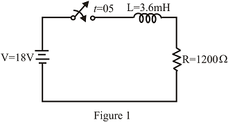
Fig. 11.81
Expert Solution & Answer
Want to see the full answer?
Check out a sample textbook solution
Students have asked these similar questions
Q.1. A power suppply having 220 V AC input and two fixed outputs as 10 V DC and 20 V DC is requested from you. For this purpose, a transformer with 220 V AC input / 15 V AC output, some capacitors, some silicon diodes, and zener diodes are presented.a) Design your power supply and point out DC voltage outputs
b) Explain the operation of the network and all the components used in the design .c) Calculate and plot input and output signals of the network.Hint: For design, remember clipper, clamper, rectifier,voltage multiplier and zener circuits
Design & draw your own regulated DC power supply to convert the domestic AC
mains of 230V to charge a tablet phone which requires 10V DC input with 200mA
current.
Specify all the assumptions & ratings of the devices used from input to the output.
Circuit Diagram
Assumptions
Calculation
A bridge rectifier is connected to a transformer which takes 230V 50Hz at its input, and supplies a loadof 200 Ω. If the turns ratio of the transformer is 4:1 what will be the output voltage (DC), the peakinverse voltage and the output frequency.
Chapter 11 Solutions
Introductory Circuit Analysis (13th Edition)
Ch. 11 - For the electromagnet in Fig. 11.75: a. Find the...Ch. 11 - For the inductor in Fig. 11.76, find the...Ch. 11 - a. Repeat Problem 2 with a ferromagnetic core with...Ch. 11 - For the inductor in Fig. 11.77, find the...Ch. 11 - An air-core inductor has a total inductance of 4.7...Ch. 11 - What are the inductance and the range of expected...Ch. 11 - If the flux linking a coil of 50 turns changes at...Ch. 11 - Determine the rate of change of flux linking a...Ch. 11 - How many turns does a coil have if 42 mV are...Ch. 11 - Find the voltage induced across a coil of 22 mH if...
Ch. 11 - For the circuit of Fig. 11.78 composed of standard...Ch. 11 - For the circuit in Fig. 11.79 composed of standard...Ch. 11 - For the network of Fig. 11.80. a. Write the...Ch. 11 - Give a supply of 18 V, use standard values to...Ch. 11 - For the circuit in Fig. 11.82: a. Write the...Ch. 11 - In this problem, the effect of reversing the...Ch. 11 - For the network of Fig. 11.84: a. Find the...Ch. 11 - Prob. 18PCh. 11 - Prob. 19PCh. 11 - Prob. 20PCh. 11 - For the network in Fig. 11.88: a. Determine the...Ch. 11 - For the network in Fig. 11.89: a. Write the...Ch. 11 - Prob. 23PCh. 11 - For Fig. 11.91: a. Determine the mathematical...Ch. 11 - For Fig. 11.92: a. Determine the mathematical...Ch. 11 - For the network in Fig. 11.93, the switch is...Ch. 11 - The switch in Fig. 11.94 has been open for a long...Ch. 11 - Prob. 28PCh. 11 - The switch for the network in Fig. 11.96 has been...Ch. 11 - The switch in Fig. 11.97 has been closed for a...Ch. 11 - Given iL=100mA(1e-t/20ms) a. Determine iLatt=1ms....Ch. 11 - a. If the measured current for an inductor during...Ch. 11 - The network in Fig. 11.98 employs a DMM with an...Ch. 11 - Find the waveform for the voltage induced across a...Ch. 11 - Find the waveform for the voltage induced across a...Ch. 11 - Prob. 36PCh. 11 - Find the total inductance of the circuit of Fig....Ch. 11 - Find the total inductance for the network of Fig....Ch. 11 - Reduce the network in Fig. 11.104 to the fewest...Ch. 11 - Reduce the network in Fig. 11.105 to the fewest...Ch. 11 - Reduce the network of Fig. 11.106 to the fewest...Ch. 11 - For the network in Fig. 11.107: a. Write the...Ch. 11 - For the network in Fig. 11.108: a. Write the...Ch. 11 - For the network in Fig. 11.109. a. Find the...Ch. 11 - Find the steady-state currents I1 and I2 for the...Ch. 11 - Find the steady-state currents and voltages for...Ch. 11 - Find the steady-state currents and voltages for...Ch. 11 - Find the indicated steady-state currents and...Ch. 11 - Prob. 49PCh. 11 - Using PSpice or Multisim, verify the results of...Ch. 11 - Using the PSpice or Multisim, find the solution to...Ch. 11 - Using PSpice or Multisim, find the solution to...Ch. 11 - Using PSpice or Multisim, verify the results of...
Knowledge Booster


Learn more about
Need a deep-dive on the concept behind this application? Look no further. Learn more about this topic, electrical-engineering and related others by exploring similar questions and additional content below.Similar questions
- FACTS: AC-DC converters take the AC power from wall outlets and convert it to unregulated DC. These power supplies include transformers that change the voltage of the AC that comes through wall outlets, rectifiers to save it from AC to DC and a filter that removes noise from the peaks and troths of the AC power waves.The DC-to-AC Converters are used to charge the batteries in the vehicles. These circuits are mainly used for driving low-power AC motors and are used in a solar power system. The DC to AC converters can be used in dc transmission lines for transmitting power to loads. QUESTION: What do you think is the main reason why we have AC power in our outlets instead of DC power? Explain your answer.arrow_forwardFind the Vpeak of the Vout Value of the circuit below during the positive half cycle. R1 SiliconD Silicon V1 AC v2 15 0.7 0.7 V3 Voutarrow_forwardFind the Vpeak of the Vout Value of the circuit below during the negative half cycle. R1 SiliconD Silicon V1 AC V2 15 0.7 0.7 V3 Voutarrow_forward
- At room temperature (T= 300 K), the typical value of thermal voltage VT is: a. 25 MV O b. 25 V O c. 25 nV O d. 25 mVarrow_forwardWhich of the following statement is false regarding the emf? O a. The battery or other emf source always produces the same amount of current regardless of the kind of component/s in the circuit. O b. For a real source of emf, the terminal voltage equals the emf only if no current is flowing through the source. O c. The source of emf supplies a constant potential difference independent of the current in series with an internal resistance. O d. The increase in internal resistance may decrease the terminal voltage. O e. The battery may overheat due to the increased power dissipated by the internal resistance.arrow_forwardAs a electrical engineering student what is the problem in power Quality: Ensuring that the voltage and frequency of the power supplied to customers is of good quality and within the acceptable limits.arrow_forward
- Ge 10:1 m Thanks Any help will be appreciated. S BL • I am doing a AC DC 12 W Regulated power supply with 110 vrms and 60HZ as an input, and I need an output of 6v and 9 V. I have the designed already: the step-down transformer, Resistor as a current limiter to protect the Zener diode, a capacitor for the ripple voltage, and a 2 state switch ( when the switch is closed to the RL will give 9 V and when is closed to the S will give 6V as an output). • I need some support with some calculations to find PIV for each diode // Average Power// some calculations in how to find the values for the resistors and capacitors to accomplish the desire output // and some calculations for the ripple voltage. Note: the Zener is regulated to 9v. I know the RL>R to get the desire output.arrow_forwardIn Dhaka city during the month of May, a 20W rated solar panel supplies 15W of power at an output voltage of 15V & an output current of 1A. But during the month of December, the same solar panel supplies 8.5W of power at an output voltage of 10.5V & an output current of 0.81A.The solar panel is used to charge a 12V battery. Practically, for charging a 12V battery we need to supply 13V. i) In the month of May, the user will need a DC-DC converter (Buck) to charge the battery.a) What will be the duty cycle?b) Assuming that the converter is 100% efficient, what will be the input current to the battery?arrow_forwardWhich of the following elements of electrical engineering cannot be analyzed using Ohm's law? a) Capacitors b) Inductors c) Transistors d) Resistancearrow_forward
- For the simple equivalent circuit of 0.017 m2 PV cell shown below, the reverse saturatoin current is I0= 4 * 10-11 A and at an insolation of 1-sun the short circuit current is Isc = 6.4 A. At 25 degrees C, find the following: a. The open circuit voltage b. The load current and the output power when the output voltage is V = 0.55 V c. The efficiency of the cell at V=0.55 Varrow_forwardcture Moving Coil Instruments Example: Rm If PMMC meter have internal resistance of 102 and full scale range of ImA. Assume we wish to increase the meter range to 1A.arrow_forwardIn the circuit below, if the inductance L is large enough to operate in continuous current mode. a) Draw the waveform of the output voltage and mains current for the 45 degree trigger angle when the switch S is in transmission. b) Average value of output DA voltage VDC1 when switch S is open, output DA when switch S is closed (in transmission) If the average value of the voltage is VDC2, calculate the value of VDC1 / VDC2. Lesson: power electronics please quickarrow_forward
arrow_back_ios
SEE MORE QUESTIONS
arrow_forward_ios
Recommended textbooks for you
 Introductory Circuit Analysis (13th Edition)Electrical EngineeringISBN:9780133923605Author:Robert L. BoylestadPublisher:PEARSON
 Delmar's Standard Textbook Of ElectricityElectrical EngineeringISBN:9781337900348Author:Stephen L. HermanPublisher:Cengage Learning
 Programmable Logic ControllersElectrical EngineeringISBN:9780073373843Author:Frank D. PetruzellaPublisher:McGraw-Hill Education
 Fundamentals of Electric CircuitsElectrical EngineeringISBN:9780078028229Author:Charles K Alexander, Matthew SadikuPublisher:McGraw-Hill Education
 Electric Circuits. (11th Edition)Electrical EngineeringISBN:9780134746968Author:James W. Nilsson, Susan RiedelPublisher:PEARSON
 Engineering ElectromagneticsElectrical EngineeringISBN:9780078028151Author:Hayt, William H. (william Hart), Jr, BUCK, John A.Publisher:Mcgraw-hill Education,
Introductory Circuit Analysis (13th Edition)
Electrical Engineering
ISBN:9780133923605
Author:Robert L. Boylestad
Publisher:PEARSON
Delmar's Standard Textbook Of Electricity
Electrical Engineering
ISBN:9781337900348
Author:Stephen L. Herman
Publisher:Cengage Learning
Programmable Logic Controllers
Electrical Engineering
ISBN:9780073373843
Author:Frank D. Petruzella
Publisher:McGraw-Hill Education
Fundamentals of Electric Circuits
Electrical Engineering
ISBN:9780078028229
Author:Charles K Alexander, Matthew Sadiku
Publisher:McGraw-Hill Education
Electric Circuits. (11th Edition)
Electrical Engineering
ISBN:9780134746968
Author:James W. Nilsson, Susan Riedel
Publisher:PEARSON
Engineering Electromagnetics
Electrical Engineering
ISBN:9780078028151
Author:Hayt, William H. (william Hart), Jr, BUCK, John A.
Publisher:Mcgraw-hill Education,
How do Universal Motors work ?; Author: Lesics;https://www.youtube.com/watch?v=0PDRJKz-mqE;License: Standard Youtube License