
Videos
Consider the transformer−coupled emitter follower in Figure P8.36. Assume an ideal transformer. The transistor parameters are
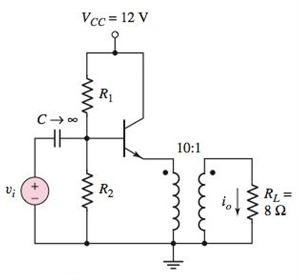
Figure P8.36
Want to see the full answer?
Check out a sample textbook solution
Chapter 8 Solutions
Microelectronics: Circuit Analysis and Design


- 3. Write down which transistor structure each curve characteristic belongs to in the figure. Ip -VGS -VGS +VGs (c) VGS (b) (a)arrow_forwardDescribe different control schemes of AC regulators and derive the expressions of average and effective values of output voltages.arrow_forward4. The power dissipated in a resistance is equal to ..in non-sinusoidal input signal.arrow_forward
- A signal generator having a source resistance of 50 2 is set to generate a 1 kHz sinewave. Open circuit terminal voltage is 10 V peak-to-peak. Connecting a capacitor. across the terminals reduces the voltage to 8 V peak-to-peak. The value of this capacitor is -HF. (Round off to 2 decimal places).arrow_forward6.8. In a single-phase mid-point converter, turns ratio from primary to each secondary is 1.25. The source voltage is 230 V, 50 Hz. For a resistive load of R = 2 2, determine (a) maximum value of average output voltage and load current and the corresponding firing and conduction angles, (b) maximum average and rms thyristor currents, (c) maximum possible values of positive and negative voltages across SCRs, (d) the value of a for load voltage of 100 V, (e) the value of voltage across SCR at the instant of commutation for a of part (d). Hint. (b) Maximum average thyristor current =; So 2n 0 [Ans. (a) 165.63 V, V. m R sin o d(at) etc. 82.82 A, a=0°, y= 180° (b) 41.41 A, 65.054 A (c) 520.4 V. 520.4 V (d) 52,862° (e) 414.82 V]arrow_forward1. The DC-DC converter has several circuit configurations. a) (Draw a simple connection of IGBT switch, diode and inductor that can discriminate between Buck, Boost and Buck-Boost converter circuits respectively.) b) ('A Boost converter produces an output voltage, Vo that is more than or equal to the input voltage, Vi. Based on this statement develop the equation for the relationship between Vo Viand D. where D represents the duty ratio. You can use any suitable diagram to illustrate your answer.)arrow_forward
- The circuit diagram of step-up type DC-DC converter is given below. It is assumed that the output capacitor is large enough and the output voltage is constant. (Consider that there is no circuit losses.) What should the inductance value be in order for the circuit to always operate in the Intermittent Current Mode (DCM)?Calculate.arrow_forward4. The average power consumed by a resistance is equal to .. in non- .... ... sinusoidal input signal. *arrow_forwardQUESTION 4 In this voltage divider bias circuit, the input is at the base. Output is at the emitter with a high input resistance and low output resistance. The maximum voltage gain is 1 and the coupling capacitors must have a negligible reactance at the frequency of operation. (use to answer a and b) a. Derive the expression for the voltage gain, current gain, and power gain in terms of power delivered to the load, RL. b. Sketch both the DC and AC equivalent circuits. c. Derive the expression for ripple factor of Half Wave Rectification with a capacitor filter.arrow_forward
- 9. Design a biased-transistor circuit using VBB = Vcc= 10 V for a Q-point of Ic = 5 mA and VCE 4 V. Assume pc = 100. The design involves finding RB, RC, and the minimum power rating of the transistor. (The actual power rating should be greater.) Sketch the circuit.arrow_forwardfor the Steady-State Operation of Buck DC-DC Converter Describe the nature of the current through the equivalent series resistance (ESR) of the capacitor. What is the effect on the shape of the current when the value of the ESR is increased?arrow_forwardA resistor Ra is in series with a voltage source Va. Draw the circuit. Label the voltage across the combination as v and the current as i. Draw and label the volt–ampere characteristic (i versus v).arrow_forward
 Introductory Circuit Analysis (13th Edition)Electrical EngineeringISBN:9780133923605Author:Robert L. BoylestadPublisher:PEARSON
 Delmar's Standard Textbook Of ElectricityElectrical EngineeringISBN:9781337900348Author:Stephen L. HermanPublisher:Cengage Learning
 Programmable Logic ControllersElectrical EngineeringISBN:9780073373843Author:Frank D. PetruzellaPublisher:McGraw-Hill Education
 Fundamentals of Electric CircuitsElectrical EngineeringISBN:9780078028229Author:Charles K Alexander, Matthew SadikuPublisher:McGraw-Hill Education
 Electric Circuits. (11th Edition)Electrical EngineeringISBN:9780134746968Author:James W. Nilsson, Susan RiedelPublisher:PEARSON
 Engineering ElectromagneticsElectrical EngineeringISBN:9780078028151Author:Hayt, William H. (william Hart), Jr, BUCK, John A.Publisher:Mcgraw-hill Education,