
Concept explainers
Videos
Consider the class−AB output stage in Figure P8.28. The diodes and transistors arc matched, with parameters
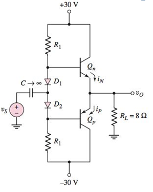
Figure P8.28
Want to see the full answer?
Check out a sample textbook solution
Chapter 8 Solutions
Microelectronics: Circuit Analysis and Design


- Show the downward shift of the output signal with the series capacitor and diode. Clampers or DC restorers are clamp a peak of a waveform to a specific DC level compared with a capacitively coupled signal which swings about its average DC level (usually 0V). If the diode is removed from the clamper, it defaults to a simple coupling capacitor– no clamping. What is the clamp voltage? And, which peak gets clamped? Why is this so? Produce a schematic diagram with LTspice schematic capture program. Voltage values: Capasitor value: 1000 pF DC offset: 0 V Amplitude: 5 V Freq: 1 KHzarrow_forwardAssuming the diodes to be ideal. For the circuit shown below: (a) Find the transfer characteristics (vO vs vI) of the circuit. (b) Draw the transfer characteristics (vO vs vI).arrow_forwardConsider the half-wave rectifier shown below. It needs to deliver 0.1 A and an average of 15 V to a load. The source is 60 Hz and the diode has a 0.7 V drop. The allowable ripple is no more than 0.4 V (2.5%). Find: Peak AC voltage Vm of the source a) b) The minimum value of the smoothing capacitor(s) c) Comment on the type of capacitor and its/their values you would use for this amount of capacitance vs(t) K Load ULarrow_forward
- Show the output voltage for the input voltage Vi in the figure by plotting it over a period. (Note: the diode used is a silicon diode and will not be considered ideal.)arrow_forwardConsider the half-wave rectifier shown below. It needs to deliver 0.1 A and an average of 15 V to a load. The source is 60 Hz and the diode has a 0.7 V drop. The allowable ripple is no more than 0.4 V (2.5%). Find: a) Peak AC voltage Vm of the source b) The minimum value of the smoothing capacitor(s) c) Comment on the type of capacitor and its/their values you would use for this amount of capacitancearrow_forwardAssume the diodes to be ideal ,descibe the transfer functionality for the following circuit.arrow_forward
- Sketch current I vs, voltage V for the circuits below. The breakdown voltage of the Zener diodes are shown. Assume 0.6V for all diodes (including Zener diodes) in the forward bias region.arrow_forwardA R-load half-wave rectifier used sinusoidal voltage source with a peak value (35.353kV). The firing angle is (30). The total resistance is 50k2 and frequency is 50HZ. Calculate (in details): load direct voltage, maximum direct voltage, normalized voltage and effective voltage, power delivered to the load, power factor, form factor, ripple factor?arrow_forwardZener diodes are special purpose diodes designed to operate in their breakdown regions. Describe the working principle and characteristics of a typical Zener diode found in the market place. The Zener-diode regulator circuit shown below is to be used to provide a stabilised output to the load. The zener diode characteristic is also shown. Find the load voltage and source current if the battery voltage is 20 V, series resistance is 1.4 kohm and load resistance is 6 kohmarrow_forward
- Consider the circuit of Figure P8.7. Determine whether the diode is conducting. Assume VÀ = 12V, VB = 10V, and that the diode is ideal. 592 ww Determine whether the diode is conducting or not. 102 wwwarrow_forwardRefer to the circuit. Consider ideal model (V_D=0) of diode circuits. Given V_i =100 Volts peak-to-peak sinusoidal input (+50, -50 Voltage peaks). Determine the peak output voltage during the diode non-conduction cycle.arrow_forwardConsider the following circuit (See image):Show that it is a unity gain absolute value circuit, consider ideal diodesarrow_forward
 Introductory Circuit Analysis (13th Edition)Electrical EngineeringISBN:9780133923605Author:Robert L. BoylestadPublisher:PEARSON
 Delmar's Standard Textbook Of ElectricityElectrical EngineeringISBN:9781337900348Author:Stephen L. HermanPublisher:Cengage Learning
 Programmable Logic ControllersElectrical EngineeringISBN:9780073373843Author:Frank D. PetruzellaPublisher:McGraw-Hill Education
 Fundamentals of Electric CircuitsElectrical EngineeringISBN:9780078028229Author:Charles K Alexander, Matthew SadikuPublisher:McGraw-Hill Education
 Electric Circuits. (11th Edition)Electrical EngineeringISBN:9780134746968Author:James W. Nilsson, Susan RiedelPublisher:PEARSON
 Engineering ElectromagneticsElectrical EngineeringISBN:9780078028151Author:Hayt, William H. (william Hart), Jr, BUCK, John A.Publisher:Mcgraw-hill Education,