
Videos
Consider the class−AB MOSFET output stage shown in Figure P8.46. The circuit meters are
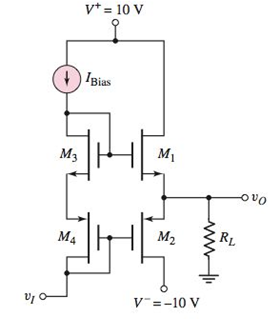
Figure P8.46
Want to see the full answer?
Check out a sample textbook solution
Chapter 8 Solutions
Microelectronics: Circuit Analysis and Design


- Complete the given BJT circuit. Solve for the value of the resistors and the voltage supply that will satisfy the given DC loadline. Assume IC=IE and RC=RE. Show and label properly the required final circuit. 5 mA 2.5 mA * IC IC 0 15 V 30V VCE RB B +VCC C E RC B=100 RE ...arrow_forward24. Set up a midpoint bias for a JFET with Ipss = 14 mA and VGs(ofm = -10 V. Use a 24 V dc source as the supply voltage. Show the circuit and resistor values. Indicate the values of Ip, VGs, and Vps-arrow_forward........ (Figure-1) R. RB= 380kN,Rc= 1kN B = 100, VBB = Vcc=12V RB ww Vec CC ......... I, V CE СЕ V ВЕ BB Q-1-b) Describe briefly the input / output characteristics and application of Common Emitter BJT Configurationarrow_forward
- Problem #6: An abrupt p-n junction varactor is used to tune an oscillator shown in Figure 3. At zero bias voltage, the varactor has a junction capacitance of 4pF, Vbi 1.3V for GaAs. The active device has CD = 2pF and RD = 10W. The load bias has L₁ = 15nH and R₁ = 10W. What are the oscillation frequencies at (a) -20V (b) -10V and (c) OV? = L₁ R₁ C₁ (V) -RD FIGURE-3 www CDarrow_forward5, a) Determine Vdsat when ID=.5 mA. b) Determine Kn when ID = 0.5 Amps. (Show your work!) c) Determine VTN. (Show your work!) d) Vgs Consider the circuit and corresponding graph, shown below. ID (mA) 0.60 0.50 0.40 0.30 0.20 0.10 0.00 0 0.5 Vds 1 1.5 2 2.5 Vds 3 3.5 4 4.5 5 -Vgs = 1V - Vgs = 1.1V - Vgs = 1.2V - Vgs = 1.3Varrow_forwardTransistor used is an NPN Transistor 1. Measure collector, base and emitter currents with DC analysis. Assign values of capacitances.2. Determine Vo/Vi using analytical solutions.3. What is the peak to peak Vo at the second stage if Vi = 15mV. 4. Verify results of Vo with analytical solutions in 3)arrow_forward
- At any point on the characteristics the product of VCE and IC must be equal to 300 mW. If we choose IC to be the maximum value of 50 mA and substitute into the relationship above, we obtain VCE=? VCEIC = 300 mW a. Reverse bias (J1) and Forward bias (J2) b. Forward bias (J1) and Reverse bias (J2) c.Reverse bias (J1) and Reverse bias (J2) d. Forward bias (J1) and Forward bias (J2)arrow_forwardin the circuit given in the figure , VDD = 20 V ,Rs= 1 kohm , VGSQ= -2.6 v, IDQ = 2.6 mA.the transistor specifically has values of IDSS = 8mA , Vp= -6 V , and gos =25 µS. what should be the RD resistance for the output voltage to be -24.85 mV when an AC voltage of 12 mV is applied to the transistor input ? Options: a) 3.3 kohm b) 4.2 kohm c) 4.5 kohm d) 3.6 kohm e) 3.9 kohmarrow_forward8.17c Copper extension leads are installed as shown in Figure 8.48b. For an output voltage of 7.947 mV and a reference junction temperature of 0⁰C, what is the temperature of the measuring junction?arrow_forward
- An emitter follower output stage has Vcc = 10 V, R3 =5 k2, VCEsat= 0.2 V, RL = 1 kQ. Assume the signals are sinusoidal. +Vec A) select R1 and R2 to make the efficiency 10% Hint: IQ must be more than IR B) If R1=R2=0. select R3 to make RL follow the situation of RL1. calculate the corresponding load power , efficiency, and the maximum instantaneous power dissipation in Q1 -Vec 21arrow_forward8.15 MECT361 Mechatronics Components and Instrumentation 8.15. Using the Internet, look up the specifications for the National Semiconductor ( www.national.com ) ADC0800 8-bit A/D converter. Determine the maximum sam- pling rate and the method for performing the conversion. Also define each of the inputs and outputs. PLEASE GIVE ME THE REFRENCE I Will get zero if you didn't put the refrencearrow_forwardFrom the figure shown, when S1 is at 1 : up position; the following statement is not correct except: (a) Collector-emitter voltage of Q1 is approximately zero (b) the LED will illuminate (c) the base voltage of Q2 is equal to 9 V (d) (b) and (c)arrow_forward
 Introductory Circuit Analysis (13th Edition)Electrical EngineeringISBN:9780133923605Author:Robert L. BoylestadPublisher:PEARSON
 Delmar's Standard Textbook Of ElectricityElectrical EngineeringISBN:9781337900348Author:Stephen L. HermanPublisher:Cengage Learning
 Programmable Logic ControllersElectrical EngineeringISBN:9780073373843Author:Frank D. PetruzellaPublisher:McGraw-Hill Education
 Fundamentals of Electric CircuitsElectrical EngineeringISBN:9780078028229Author:Charles K Alexander, Matthew SadikuPublisher:McGraw-Hill Education
 Electric Circuits. (11th Edition)Electrical EngineeringISBN:9780134746968Author:James W. Nilsson, Susan RiedelPublisher:PEARSON
 Engineering ElectromagneticsElectrical EngineeringISBN:9780078028151Author:Hayt, William H. (william Hart), Jr, BUCK, John A.Publisher:Mcgraw-hill Education,