
Introductory Circuit Analysis (13th Edition)
13th Edition
ISBN: 9780133923605
Author: Robert L. Boylestad
Publisher: PEARSON
expand_more
expand_more
format_list_bulleted
Concept explainers
Videos
Textbook Question
Chapter 5, Problem 26P
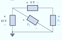
Using Kirchhoff’s voltage law, determine the unknown voltages for the series circuits in Fig. 5.113.
Expert Solution & Answer
Want to see the full answer?
Check out a sample textbook solution
Students have asked these similar questions
53. Obtain an expression for i(t) as labeled in the circuit diagram of Fig. 8.84, and
determine the power being dissipated in the 40 2 resistor at t = 2.5 ms.
t=0
i(t)
30 Ω
w
200 mA 4002
30 m
100 mA(
7.2
At t = 0, the switch in the circuit shown moves
instantaneously from position a to position b.
a) Calculate v, for t≥ 0.
b) What percentage of the initial energy stored
in the inductor is eventually dissipated in
the 4
resistor?
6Ω
a
w
+
10 0.32 H3 403
6.4 A
=0
b
Answer: (a) -8e-10 V, t = 0;
(b) 80%.
At t = 0, the switch closes. Find the IL(t) and VL(t) for t≥ 0 in t and s domain.
Can you help me?
1)
(+.
24V
ง
Anahtar t=0 anında kapatılıyor.
to icin TL(t) ve
bulunuz.
J
3√√√2
ww
مفروم
+
t=0
$6.5 5H VLCH) 2.2
Vilt)
Chapter 5 Solutions
Introductory Circuit Analysis (13th Edition)
Ch. 5 - For each configuration in Fig. 5.88, find the...Ch. 5 - For each configuration in Fig. 5.89, find the...Ch. 5 - Find the total resistance RT for each...Ch. 5 - Find the total resistance RT for each...Ch. 5 - For each circuit board in Fig. 5.92, �nd the...Ch. 5 - For the circuit in Fig. 5.93, composed of standard...Ch. 5 - For each configuration in Fig. 5.94, determine the...Ch. 5 - Find the resistance R, given the ohmmeter reading...Ch. 5 - What is the ohmmeter reading for each...Ch. 5 - For the series configuration in Fig. 5.97,...
Ch. 5 - For the series configuration in Fig. 5.98,...Ch. 5 - Find the applied voltage necessary to develop the...Ch. 5 - For each network in Fig. 5.100, constructed of...Ch. 5 - For each configuration in Fig. 5.101, what are the...Ch. 5 - For each configuration of Fig. 5.102, find the...Ch. 5 - For the circuit in Fig. 5.103, constructed of...Ch. 5 - Find the unknown quantities for the circuit of...Ch. 5 - Find the unknown quantities for the circuit in...Ch. 5 - Eight holiday lights are connected in series as...Ch. 5 - For the conditions specified in Fig. 5.107,...Ch. 5 - Combine the series voltage sources in Fig. 5.108,...Ch. 5 - Determine the current I and its direction for each...Ch. 5 - Find {he unknown voltage source and resistor for...Ch. 5 - Using Kirchhoffs voltage law, find the unknown...Ch. 5 - Find the current I for the network of Fig. 5.112....Ch. 5 - Using Kirchhoffs voltage law, determine the...Ch. 5 - Using Kirchhoffs voltage law, find the unknown...Ch. 5 - Determine the values of the unknown resistors in...Ch. 5 - For the configuration in Fig. 5.116, with standard...Ch. 5 - Using the voltage divider rule, find the indicated...Ch. 5 - Using the voltage divider rule or Kirchhoffs...Ch. 5 - Using the voltage divider rule or Kirchhoffs...Ch. 5 - Using the information provided, find the unknown...Ch. 5 - Using the voltage divider rule, �nd the unknown...Ch. 5 - Design a voltage divider circuit that will permit...Ch. 5 - Design the voltage divider in Fig. 5.122 such that...Ch. 5 - Find the voltage across each resistor in Fig....Ch. 5 - Design the circuit in Fig. 5.124 such that...Ch. 5 - Determine the voltages Va,Vb, and Vab for the...Ch. 5 - Determine the current I (with direction) and the...Ch. 5 - For the network in Fig. 5.127 determine the...Ch. 5 - Given the information appearing in Fig. 5.128,...Ch. 5 - Determine the values of R1,R2,R3, and R4 for the...Ch. 5 - For the network in Fig. 5.130, determine the...Ch. 5 - For the integrated circuit in Fig. 5.131,...Ch. 5 - For the integrated circuit in Fig. 5.132,...Ch. 5 - Find the internal resistance of a battery that has...Ch. 5 - Find the voltage to the load (full-and conditions)...Ch. 5 - Determine the current through the circuit in Fig....Ch. 5 - Use the computer to verify the results of Example...Ch. 5 - Use the computer to verify the results of Example...Ch. 5 - Use the computer to verify the results of Example...
Additional Engineering Textbook Solutions
Find more solutions based on key concepts
How does a computers main memory differ from its auxiliary memory?
Java: An Introduction to Problem Solving and Programming (8th Edition)
How is the hydrodynamic entry length defined for flow in a pipe? Is the entry length longer in laminar or turbu...
Fluid Mechanics: Fundamentals and Applications
Using your text editor, enter (that is, type in) the C++ program shown in Display 1.8. Be certain to type the f...
Problem Solving with C++ (10th Edition)
This optional Google account security feature sends you a message with a code that you must enter, in addition ...
SURVEY OF OPERATING SYSTEMS
Consider the adage Never ask a question for which you do not want the answer. a. Is following that adage ethica...
Experiencing MIS
1.2 Explain the difference between geodetic and plane
surveys,
Elementary Surveying: An Introduction To Geomatics (15th Edition)
Knowledge Booster


Learn more about
Need a deep-dive on the concept behind this application? Look no further. Learn more about this topic, electrical-engineering and related others by exploring similar questions and additional content below.Similar questions
- "For the network in the figure, determine RE and RB if A₁ Zb = BRE." = -10 and re = 3.8. Assume thatarrow_forward2.a. Simplify and determine Zk+ for: 2.x. 60 [Hz] ⚫ 2.y. 180 [Hz] a.x. 60[Hz] a.y. 180 [Hz] Joo (127 2[H] w 240 [√]arrow_forwardP3. Given the following network, determine: ⚫ 3.a. Equivalent Y ⚫ 3.b. Equivalent A 2 R[2] 10 8 b 20 30 5arrow_forward
- [Electrical Circuits] P1. Using the mesh current method, calculate the magnitude and direction of: 1.a. I and I (mesh currents) 1.b. I10 (test current in R10 = 1082) 1.c. (Calculate the magnitude and signs of V10) 6[A] 12 [√] بي 10 38 20 4A] Iw -800arrow_forwardNeed handwritten solution do not use chatgptarrow_forward[07/01, 16:59] C P: Question: Calculate the following for 100Hz and 500Hz (express all answers in phasor form). Show all work. A) Xc and ZTB) VR1 and VC1 C) IT Handwritten Solution Pleasearrow_forward
- 1. Sketch the root loci of a system with the following characteristic equation: s²+2s+2+K(s+2)=0 2. Sketch the root loci for the following loop transfer function: KG(s)H(s)=- K(s+1) s(s+2)(s²+2s+4)arrow_forward3. For the unity feedback system with forward path transfer function, G(s), below: G(s)= K(s² +8) (s+4)(s+5) Sketch the root locus and show the breakaway/break-in point(s) and jo-axis crossing. Determine the angle of arrival and K value at the breakaway/break- in point(s). Give your comment the system is stable or unstable.arrow_forwardFind the step response of each of the transfer functions shown in Eqs. (4.62) through (4.64) and compare them. [Shown in the image]Book: Norman S. Nise - Control Systems Engineering, 6th EditionTopic: Chapter-4: Time Response, Example 4.8Solve the math with proper explanation. Please don't give AI response. Asking for a expert verified answer.arrow_forward
- 2. With respect to the circuit shown in Figure 2 below V2 -R1 R2 R4 w R3 R5 Figure 2: DC Circuit 2 a. Using Ohm's and Kirchhoff's laws calculate the current flowing through R3 and so determine wattage rating of R3. b. Verify your results with simulations. Note: you must use the values for the components in Table 2. Table 2 V2 (Volts) R1 (KQ) R2 (KQ) R3 (KQ) R4 (KQ) R5 (KQ) 9 3.3 5 10 6 1 3.3arrow_forwardDon't use ai to answer i will report your answerarrow_forwardDon't use ai to answer I will report you answerarrow_forward
arrow_back_ios
SEE MORE QUESTIONS
arrow_forward_ios
Recommended textbooks for you
 Delmar's Standard Textbook Of ElectricityElectrical EngineeringISBN:9781337900348Author:Stephen L. HermanPublisher:Cengage Learning
Delmar's Standard Textbook Of Electricity
Electrical Engineering
ISBN:9781337900348
Author:Stephen L. Herman
Publisher:Cengage Learning
Kirchhoff's Rules of Electrical Circuits; Author: Flipping Physics;https://www.youtube.com/watch?v=d0O-KUKP4nM;License: Standard YouTube License, CC-BY