
Introductory Circuit Analysis (13th Edition)
13th Edition
ISBN: 9780133923605
Author: Robert L. Boylestad
Publisher: PEARSON
expand_more
expand_more
format_list_bulleted
Concept explainers
Videos
Textbook Question
Chapter 5, Problem 16P
For the circuit in Fig. 5.103, constructed of standard value resistors:
- Find the total resistance, current, and voltage across each element.
- Find the power delivered to each resistor.
- Calculate the total power delivered to all the resistors.
- Find the power delivered by the source.
- How does the power delivered by the source compare to that delivered to all the resistors?
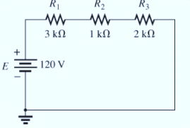
- Which resistor received the most power? Why?
- What happened to all the power delivered to the resistors?
- If the resistors are available with wattage ratings of 1/2 W, 1 W, 2 W, and 5 W, what minimum wattage rating can be used for each resistor?
Expert Solution & Answer

Learn your wayIncludes step-by-step video

schedule07:34
Students have asked these similar questions
5. Manufacturers recommend always powering devices using batteries of the same brand and
freshness. This is important. Batteries change voltage as they discharge, which can cause
old batteries to drag down new ones. To illustrate this, consider the circuit shown below.
Show that when the load is connected, most of the current that leaves the new battery does
not go through the load.
IntRes2
200mQ
DeadChemistry
1.1V
Old Battery
IntRes1
100mQ
FreshChemistry
1.5V
NewBattery
Off
Von
LoadCircuits
1000
Calculate the equivalent resistance Rab in the given circuit.
Two practical batteries are connected in series, such that the positive terminal of one battery is connected to the positive terminal of the other battery.
Which of the following must be true?
OA. The total EMF is greater than the individual EMFS of the battery
O B. When the series combination of batteries is connected to a load, the current will be uneven throughout the circuit.
O C. The total internal resistance is equal to the sum of the individual internal resistances
O D. When the series combination of batteries is connected to a load, both batteries will be discharging.
Chapter 5 Solutions
Introductory Circuit Analysis (13th Edition)
Ch. 5 - For each configuration in Fig. 5.88, find the...Ch. 5 - For each configuration in Fig. 5.89, find the...Ch. 5 - Find the total resistance RT for each...Ch. 5 - Find the total resistance RT for each...Ch. 5 - For each circuit board in Fig. 5.92, �nd the...Ch. 5 - For the circuit in Fig. 5.93, composed of standard...Ch. 5 - For each configuration in Fig. 5.94, determine the...Ch. 5 - Find the resistance R, given the ohmmeter reading...Ch. 5 - What is the ohmmeter reading for each...Ch. 5 - For the series configuration in Fig. 5.97,...
Ch. 5 - For the series configuration in Fig. 5.98,...Ch. 5 - Find the applied voltage necessary to develop the...Ch. 5 - For each network in Fig. 5.100, constructed of...Ch. 5 - For each configuration in Fig. 5.101, what are the...Ch. 5 - For each configuration of Fig. 5.102, find the...Ch. 5 - For the circuit in Fig. 5.103, constructed of...Ch. 5 - Find the unknown quantities for the circuit of...Ch. 5 - Find the unknown quantities for the circuit in...Ch. 5 - Eight holiday lights are connected in series as...Ch. 5 - For the conditions specified in Fig. 5.107,...Ch. 5 - Combine the series voltage sources in Fig. 5.108,...Ch. 5 - Determine the current I and its direction for each...Ch. 5 - Find {he unknown voltage source and resistor for...Ch. 5 - Using Kirchhoffs voltage law, find the unknown...Ch. 5 - Find the current I for the network of Fig. 5.112....Ch. 5 - Using Kirchhoffs voltage law, determine the...Ch. 5 - Using Kirchhoffs voltage law, find the unknown...Ch. 5 - Determine the values of the unknown resistors in...Ch. 5 - For the configuration in Fig. 5.116, with standard...Ch. 5 - Using the voltage divider rule, find the indicated...Ch. 5 - Using the voltage divider rule or Kirchhoffs...Ch. 5 - Using the voltage divider rule or Kirchhoffs...Ch. 5 - Using the information provided, find the unknown...Ch. 5 - Using the voltage divider rule, �nd the unknown...Ch. 5 - Design a voltage divider circuit that will permit...Ch. 5 - Design the voltage divider in Fig. 5.122 such that...Ch. 5 - Find the voltage across each resistor in Fig....Ch. 5 - Design the circuit in Fig. 5.124 such that...Ch. 5 - Determine the voltages Va,Vb, and Vab for the...Ch. 5 - Determine the current I (with direction) and the...Ch. 5 - For the network in Fig. 5.127 determine the...Ch. 5 - Given the information appearing in Fig. 5.128,...Ch. 5 - Determine the values of R1,R2,R3, and R4 for the...Ch. 5 - For the network in Fig. 5.130, determine the...Ch. 5 - For the integrated circuit in Fig. 5.131,...Ch. 5 - For the integrated circuit in Fig. 5.132,...Ch. 5 - Find the internal resistance of a battery that has...Ch. 5 - Find the voltage to the load (full-and conditions)...Ch. 5 - Determine the current through the circuit in Fig....Ch. 5 - Use the computer to verify the results of Example...Ch. 5 - Use the computer to verify the results of Example...Ch. 5 - Use the computer to verify the results of Example...
Additional Engineering Textbook Solutions
Find more solutions based on key concepts
The switch in the bottom loop of Fig. P6.1 is closed at t = 0 and then opened at a later time t1. What is the d...
Fundamentals of Applied Electromagnetics (7th Edition)
Broadly speaking, what are the two main objectives of electrical systems?
Electrical Engineering: Principles & Applications (7th Edition)
The data shown in the following graph was collected during testing of an electromagnetic mass driver. The energ...
Thinking Like an Engineer: An Active Learning Approach (4th Edition)
Write a program that determines whether your particular computer performs an arithmetic or a logical right shif...
Programming in C
Write a parameterized constructor for a base class named Movie with a string field named _title and an int fiel...
Starting out with Visual C# (4th Edition)
Modify the temperature conversion program to print a heading above the table.
C Programming Language
Knowledge Booster


Learn more about
Need a deep-dive on the concept behind this application? Look no further. Learn more about this topic, electrical-engineering and related others by exploring similar questions and additional content below.Similar questions
- Question 5: For the two circuit given below, a. Find the total resistance, RT, and solve for the current, I, through the voltage source. b. Find all of the unknown currents in the circuit. c. Verify Kirchhoff's current law at node a. d. Determine the power dissipated by each resistor. Verify that the total power dissipated by the resistors is equal to the power delivered by the voltage source. 3.9 kfl 5.6 kfN R1 R2 100 Ω 75 Ω 43 kn 2.7 kN 270 V + 240 V 60 Ω Node a Node aarrow_forwardThe source voltage of the cell phone battery is 5.34 V. When a current of 0.29 A is taken from the battery, the value of the terminal voltage is 5.17 V. Determine a) the internal resistance of the battery, b) the power supplied by the battery to the circuit and c) the thermal power of the battery (power of the internal resistance) .arrow_forwarda. Calculate total resistance b. Calculate the total current IT c. Find the voltage VR5, with others words, the voltage drop across R5. d. Calculate IR3, in other words, the current through R3. e. Calculate the power R1 consumesarrow_forward
- construct the circuit with resistor nominal value of 91ohms, 220ohms, 330ohms, and 470 ohms.arrow_forwardFor the circuit shown in figure 5, make use of superposition as solution method. 5.1) Calculate the voltage in volts at node V0 when the 3 V source is deactivated. 5.2) Calculate the voltage in volts at node V0 when the 9 V source is deactivated. 5.3) Calculate the final voltage V0 in volts for the circuit.arrow_forward1. Find the value of Total Resistance (RT). 2. Find the value of Total Current (IT).arrow_forward
- Find the Total Current ,Equivalent Resistance, Power of the circuit.arrow_forwardDraw a schematic (circuit) diagram of four resistors connected to a source (EMF) , where should have the same current with the total current in the circuit, while share this total amount of current at the same time. have the same values with the following color bands: red, black, red, gold; while also have the same values with the following color bands: yellow, violet, brown, gold. Applying the rules in series and parallel circuits as well as Ohm's law, discuss your complete solution conceptually and mathematically. In your own words, discuss comprehensively your strategic analysis on how to solve the problem. Show logical and systematic computations to solve for the unknowns. Present your evaluated data (final answers) in a tabular matrix. Express your final answers in two decimal places. Use the template below.arrow_forward5.) When a resistance of 3 ohms is placed across the terminals of battery, the current is 2A. When the resistance is increased to 42 ohms, the current falls to 1 A. Find emf of battery and its internal resistance.arrow_forward
- Consider the circuit below. The battery has an emf of ℇ = 30.00 V and an internalresistance of r = 1.00 Ω.a. Find the equivalent resistance of the circuit and the current out of the battery.b. Find the terminal voltage of the battery. c. Find the current through each resistor. d. Find the potential difference across each resistor. e. Find the power dissipated by each resistor. f. Find the total power supplied by the battery.arrow_forwardINSTRUCTIONS: Solve the following problems. Show and COMPLETE solutions. Draw all CIRCUIT DIAGRAMS or the equivalent circuit (dummy circuit) as the case may be. Write your solutions on sheet/s of short bond paper. A battery is to consist of 20 identical cells. The emf of each cell is 1.5 V and the internal resistance is 0.20 ohm. This battery will be used to supply power to a 10 ohm lamp. Determine the current on the lamp if:1. The 20 cells are connected in series 2. The 20 cells are connected in parallel 3. The 20 cells are arranged 5 cells in series in 4 parallel rows.arrow_forwardA 6-Ohm resistor is connected in series to a parallel combination of two resistors, one is 30-Ohm and the other is R being unknown. Determine the value of R if: (a) the power dissipated in the 6- Ohm resistor is equal to the power in the parallel combination; (b) the power in 6-Ohm is equal to the power in R.arrow_forward
arrow_back_ios
SEE MORE QUESTIONS
arrow_forward_ios
Recommended textbooks for you
 Introductory Circuit Analysis (13th Edition)Electrical EngineeringISBN:9780133923605Author:Robert L. BoylestadPublisher:PEARSON
 Delmar's Standard Textbook Of ElectricityElectrical EngineeringISBN:9781337900348Author:Stephen L. HermanPublisher:Cengage Learning
 Programmable Logic ControllersElectrical EngineeringISBN:9780073373843Author:Frank D. PetruzellaPublisher:McGraw-Hill Education
 Fundamentals of Electric CircuitsElectrical EngineeringISBN:9780078028229Author:Charles K Alexander, Matthew SadikuPublisher:McGraw-Hill Education
 Electric Circuits. (11th Edition)Electrical EngineeringISBN:9780134746968Author:James W. Nilsson, Susan RiedelPublisher:PEARSON
 Engineering ElectromagneticsElectrical EngineeringISBN:9780078028151Author:Hayt, William H. (william Hart), Jr, BUCK, John A.Publisher:Mcgraw-hill Education,
Introductory Circuit Analysis (13th Edition)
Electrical Engineering
ISBN:9780133923605
Author:Robert L. Boylestad
Publisher:PEARSON
Delmar's Standard Textbook Of Electricity
Electrical Engineering
ISBN:9781337900348
Author:Stephen L. Herman
Publisher:Cengage Learning
Programmable Logic Controllers
Electrical Engineering
ISBN:9780073373843
Author:Frank D. Petruzella
Publisher:McGraw-Hill Education
Fundamentals of Electric Circuits
Electrical Engineering
ISBN:9780078028229
Author:Charles K Alexander, Matthew Sadiku
Publisher:McGraw-Hill Education
Electric Circuits. (11th Edition)
Electrical Engineering
ISBN:9780134746968
Author:James W. Nilsson, Susan Riedel
Publisher:PEARSON
Engineering Electromagnetics
Electrical Engineering
ISBN:9780078028151
Author:Hayt, William H. (william Hart), Jr, BUCK, John A.
Publisher:Mcgraw-hill Education,
Kirchhoff's Rules of Electrical Circuits; Author: Flipping Physics;https://www.youtube.com/watch?v=d0O-KUKP4nM;License: Standard YouTube License, CC-BY