
Introductory Circuit Analysis (13th Edition)
13th Edition
ISBN: 9780133923605
Author: Robert L. Boylestad
Publisher: PEARSON
expand_more
expand_more
format_list_bulleted
Concept explainers
Videos
Textbook Question
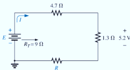
Chapter 5, Problem 13P
For each network in Fig. 5.100, constructed of standard values, determine:
- The current I.
- The source voltage E.
- The unknown resistance.
- The voltage across each element.
Expert Solution & Answer
Want to see the full answer?
Check out a sample textbook solution
Students have asked these similar questions
Compute the total resistance.
Determine the equivalent resistance for the network below
1) In the Fig. 5 – 4, between points A and B, which branch of the circuit has the greatest current flow if all resistors have the exact values indicated?a. R2, R3.b. R4c. R5d. All branch currents are the same value.
2) Which of the following would be a true statement if resistor R7 became short circuited in Fig. 5 – 4.a. Current flow would decrease.b. Voltage E AB would decrease.c. Voltage E CD would increase.d. Current flow would increase.
6. Which of the following would be a false statement if resistor R7 opened in Fig. 5 – 4?a. Current flow would decrease.b. Voltage E AB would decrease.c. Voltage E CD would increase.d. None of the above.
Chapter 5 Solutions
Introductory Circuit Analysis (13th Edition)
Ch. 5 - For each configuration in Fig. 5.88, find the...Ch. 5 - For each configuration in Fig. 5.89, find the...Ch. 5 - Find the total resistance RT for each...Ch. 5 - Find the total resistance RT for each...Ch. 5 - For each circuit board in Fig. 5.92, �nd the...Ch. 5 - For the circuit in Fig. 5.93, composed of standard...Ch. 5 - For each configuration in Fig. 5.94, determine the...Ch. 5 - Find the resistance R, given the ohmmeter reading...Ch. 5 - What is the ohmmeter reading for each...Ch. 5 - For the series configuration in Fig. 5.97,...
Ch. 5 - For the series configuration in Fig. 5.98,...Ch. 5 - Find the applied voltage necessary to develop the...Ch. 5 - For each network in Fig. 5.100, constructed of...Ch. 5 - For each configuration in Fig. 5.101, what are the...Ch. 5 - For each configuration of Fig. 5.102, find the...Ch. 5 - For the circuit in Fig. 5.103, constructed of...Ch. 5 - Find the unknown quantities for the circuit of...Ch. 5 - Find the unknown quantities for the circuit in...Ch. 5 - Eight holiday lights are connected in series as...Ch. 5 - For the conditions specified in Fig. 5.107,...Ch. 5 - Combine the series voltage sources in Fig. 5.108,...Ch. 5 - Determine the current I and its direction for each...Ch. 5 - Find {he unknown voltage source and resistor for...Ch. 5 - Using Kirchhoffs voltage law, find the unknown...Ch. 5 - Find the current I for the network of Fig. 5.112....Ch. 5 - Using Kirchhoffs voltage law, determine the...Ch. 5 - Using Kirchhoffs voltage law, find the unknown...Ch. 5 - Determine the values of the unknown resistors in...Ch. 5 - For the configuration in Fig. 5.116, with standard...Ch. 5 - Using the voltage divider rule, find the indicated...Ch. 5 - Using the voltage divider rule or Kirchhoffs...Ch. 5 - Using the voltage divider rule or Kirchhoffs...Ch. 5 - Using the information provided, find the unknown...Ch. 5 - Using the voltage divider rule, �nd the unknown...Ch. 5 - Design a voltage divider circuit that will permit...Ch. 5 - Design the voltage divider in Fig. 5.122 such that...Ch. 5 - Find the voltage across each resistor in Fig....Ch. 5 - Design the circuit in Fig. 5.124 such that...Ch. 5 - Determine the voltages Va,Vb, and Vab for the...Ch. 5 - Determine the current I (with direction) and the...Ch. 5 - For the network in Fig. 5.127 determine the...Ch. 5 - Given the information appearing in Fig. 5.128,...Ch. 5 - Determine the values of R1,R2,R3, and R4 for the...Ch. 5 - For the network in Fig. 5.130, determine the...Ch. 5 - For the integrated circuit in Fig. 5.131,...Ch. 5 - For the integrated circuit in Fig. 5.132,...Ch. 5 - Find the internal resistance of a battery that has...Ch. 5 - Find the voltage to the load (full-and conditions)...Ch. 5 - Determine the current through the circuit in Fig....Ch. 5 - Use the computer to verify the results of Example...Ch. 5 - Use the computer to verify the results of Example...Ch. 5 - Use the computer to verify the results of Example...
Additional Engineering Textbook Solutions
Find more solutions based on key concepts
Analog Voltmeter Design Figure P2-98(a) shows a voltmeter circuit consisting of a D'Arsonval meter, two series ...
ANALYSIS+DESIGN OF LINEAR CIRCUITS(LL)
Does the severity of an electric shock increase ordecrease with eh of the following changes? a. A decrease in t...
Electric Motors and Control Systems
Find I0 and I1 in the circuit in Fig.P2.12.
Basic Engineering Circuit Analysis
Three point charges of equal magnitude q, that will yield a zero net electric field at the origin.
Engineering Electromagnetics
With respect to the circuit in Fig. 5.90, (a) employ Thévenin’s theorem to determine the equivalent network see...
Loose Leaf for Engineering Circuit Analysis Format: Loose-leaf
The voltage source of the circuit shown in Fig. P1.29 is given by s(t)=25cos(4104t45)(V). Obtain an expression ...
Fundamentals of Applied Electromagnetics (7th Edition)
Knowledge Booster


Learn more about
Need a deep-dive on the concept behind this application? Look no further. Learn more about this topic, electrical-engineering and related others by exploring similar questions and additional content below.Similar questions
- A drawing office 10mX 5m having illumination of 200 Im/m2 which is to be provided by a number of 50 W lamp. Determine the number of required lamps if luminous efficiency of each lamps 10 Im/W.Consider both utilization and depreciation factors to be 1. Select one: O a 20 lamps O b. 10 lamps O. 100 lampsarrow_forward2. Using LKV Meshes and LKI Nodes, determine the circuit currents, the voltage at each one of the resistors and the power consumed by each resistor.arrow_forwardFor the next network of the picture. Calculate the current of the mail, and to determine the potency that dissipate the resistences R1, R2 and R5arrow_forward
- Compute for the following values from each item. Show complete solutions. Thevenin’s Equivalent ; Find the following: a. VTh b. RTh c. iL d. Circuit Equivalentarrow_forwardInclude an illustration of the circuit in the solutions. Thank youarrow_forwardFor the circuit in Problem 5, calculate the equivalent Thevenin voltage, Voc, in Volts as for the following circuit. Put your values in N in box below. Round off the decimals to three places if needed. Rth wwww Vocarrow_forward
- The circuits branch is defined as: Select one: a. a single path in a network, composed of one source and parallel resistor and a node at each end of the elements. b. a single path in a network, composed of two parallel elements and the node at each end of that element. C. None of the above. d. a single path in a network, composed of one simple element and the node at each end of that element. Previous page Next page Dump to,.. Return to: General +arrow_forwardTwo practical batteries are connected in series, such that the positive terminal of one battery is connected to the positive terminal of the other battery. Which of the following must be true? OA. The total EMF is greater than the individual EMFS of the battery O B. When the series combination of batteries is connected to a load, the current will be uneven throughout the circuit. O C. The total internal resistance is equal to the sum of the individual internal resistances O D. When the series combination of batteries is connected to a load, both batteries will be discharging.arrow_forwardusing Circuit Wizard, please make a simple circuit diagram of Half Subtractor.arrow_forward
- A drawing office 10m X 5m having illumination of 200 Im/m2 which is to be provided by a number of 50 W lamp. Determine the number of required lamps if luminous efficiency of each lamps 10 Im/W. Consider both utilization and depreciation factors to be 1. Select one: O a. 20 lamps O b. 100 lamps O c. 10 lampsarrow_forwardThe source voltage of the cell phone battery is 5.34 V. When a current of 0.29 A is taken from the battery, the value of the terminal voltage is 5.17 V. Determine a) the internal resistance of the battery, b) the power supplied by the battery to the circuit and c) the thermal power of the battery (power of the internal resistance) .arrow_forward1. Discuss how the circuit worksarrow_forward
arrow_back_ios
SEE MORE QUESTIONS
arrow_forward_ios
Recommended textbooks for you
 Introductory Circuit Analysis (13th Edition)Electrical EngineeringISBN:9780133923605Author:Robert L. BoylestadPublisher:PEARSON
 Delmar's Standard Textbook Of ElectricityElectrical EngineeringISBN:9781337900348Author:Stephen L. HermanPublisher:Cengage Learning
 Programmable Logic ControllersElectrical EngineeringISBN:9780073373843Author:Frank D. PetruzellaPublisher:McGraw-Hill Education
 Fundamentals of Electric CircuitsElectrical EngineeringISBN:9780078028229Author:Charles K Alexander, Matthew SadikuPublisher:McGraw-Hill Education
 Electric Circuits. (11th Edition)Electrical EngineeringISBN:9780134746968Author:James W. Nilsson, Susan RiedelPublisher:PEARSON
 Engineering ElectromagneticsElectrical EngineeringISBN:9780078028151Author:Hayt, William H. (william Hart), Jr, BUCK, John A.Publisher:Mcgraw-hill Education,
Introductory Circuit Analysis (13th Edition)
Electrical Engineering
ISBN:9780133923605
Author:Robert L. Boylestad
Publisher:PEARSON
Delmar's Standard Textbook Of Electricity
Electrical Engineering
ISBN:9781337900348
Author:Stephen L. Herman
Publisher:Cengage Learning
Programmable Logic Controllers
Electrical Engineering
ISBN:9780073373843
Author:Frank D. Petruzella
Publisher:McGraw-Hill Education
Fundamentals of Electric Circuits
Electrical Engineering
ISBN:9780078028229
Author:Charles K Alexander, Matthew Sadiku
Publisher:McGraw-Hill Education
Electric Circuits. (11th Edition)
Electrical Engineering
ISBN:9780134746968
Author:James W. Nilsson, Susan Riedel
Publisher:PEARSON
Engineering Electromagnetics
Electrical Engineering
ISBN:9780078028151
Author:Hayt, William H. (william Hart), Jr, BUCK, John A.
Publisher:Mcgraw-hill Education,
Kirchhoff's Rules of Electrical Circuits; Author: Flipping Physics;https://www.youtube.com/watch?v=d0O-KUKP4nM;License: Standard YouTube License, CC-BY