
Introductory Circuit Analysis (13th Edition)
13th Edition
ISBN: 9780133923605
Author: Robert L. Boylestad
Publisher: PEARSON
expand_more
expand_more
format_list_bulleted
Concept explainers
Videos
Textbook Question
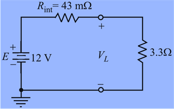
Chapter 5, Problem 48P
- Find the voltage to the load (full-and conditions) for the supply in Fig. 5.133.
- Find the voltage regulation of the supply.
- How much power is supplied by the source and lost to the internal resistance under full-load conditions?
Expert Solution & Answer
Want to see the full answer?
Check out a sample textbook solution
Students have asked these similar questions
Q5.
Determine the unknown voltages V₁ and V₂ by using Kirchhoff's
Voltage Law in Fig. 5.
20 V
+ V₁
www
www
- IV +
10 V
+ 2 V
www
ww
- V₂ +
Fig. 5
5.) When a resistance of 3 ohms is
placed across the terminals of
battery, the current is 2A. When
the resistance is increased to 42
ohms, the current falls to 1 A. Find
emf of battery and its internal
resistance.
The variable resistor (RL) in the circuit is adjusted for maximum powertransfer to RL.a) Find the numerical value of RL.b) Calculate the power for the dependent voltage source and determine if itabsorbs or supplies power.b) Find the maximum power transferred to RL.
Chapter 5 Solutions
Introductory Circuit Analysis (13th Edition)
Ch. 5 - For each configuration in Fig. 5.88, find the...Ch. 5 - For each configuration in Fig. 5.89, find the...Ch. 5 - Find the total resistance RT for each...Ch. 5 - Find the total resistance RT for each...Ch. 5 - For each circuit board in Fig. 5.92, �nd the...Ch. 5 - For the circuit in Fig. 5.93, composed of standard...Ch. 5 - For each configuration in Fig. 5.94, determine the...Ch. 5 - Find the resistance R, given the ohmmeter reading...Ch. 5 - What is the ohmmeter reading for each...Ch. 5 - For the series configuration in Fig. 5.97,...
Ch. 5 - For the series configuration in Fig. 5.98,...Ch. 5 - Find the applied voltage necessary to develop the...Ch. 5 - For each network in Fig. 5.100, constructed of...Ch. 5 - For each configuration in Fig. 5.101, what are the...Ch. 5 - For each configuration of Fig. 5.102, find the...Ch. 5 - For the circuit in Fig. 5.103, constructed of...Ch. 5 - Find the unknown quantities for the circuit of...Ch. 5 - Find the unknown quantities for the circuit in...Ch. 5 - Eight holiday lights are connected in series as...Ch. 5 - For the conditions specified in Fig. 5.107,...Ch. 5 - Combine the series voltage sources in Fig. 5.108,...Ch. 5 - Determine the current I and its direction for each...Ch. 5 - Find {he unknown voltage source and resistor for...Ch. 5 - Using Kirchhoffs voltage law, find the unknown...Ch. 5 - Find the current I for the network of Fig. 5.112....Ch. 5 - Using Kirchhoffs voltage law, determine the...Ch. 5 - Using Kirchhoffs voltage law, find the unknown...Ch. 5 - Determine the values of the unknown resistors in...Ch. 5 - For the configuration in Fig. 5.116, with standard...Ch. 5 - Using the voltage divider rule, find the indicated...Ch. 5 - Using the voltage divider rule or Kirchhoffs...Ch. 5 - Using the voltage divider rule or Kirchhoffs...Ch. 5 - Using the information provided, find the unknown...Ch. 5 - Using the voltage divider rule, �nd the unknown...Ch. 5 - Design a voltage divider circuit that will permit...Ch. 5 - Design the voltage divider in Fig. 5.122 such that...Ch. 5 - Find the voltage across each resistor in Fig....Ch. 5 - Design the circuit in Fig. 5.124 such that...Ch. 5 - Determine the voltages Va,Vb, and Vab for the...Ch. 5 - Determine the current I (with direction) and the...Ch. 5 - For the network in Fig. 5.127 determine the...Ch. 5 - Given the information appearing in Fig. 5.128,...Ch. 5 - Determine the values of R1,R2,R3, and R4 for the...Ch. 5 - For the network in Fig. 5.130, determine the...Ch. 5 - For the integrated circuit in Fig. 5.131,...Ch. 5 - For the integrated circuit in Fig. 5.132,...Ch. 5 - Find the internal resistance of a battery that has...Ch. 5 - Find the voltage to the load (full-and conditions)...Ch. 5 - Determine the current through the circuit in Fig....Ch. 5 - Use the computer to verify the results of Example...Ch. 5 - Use the computer to verify the results of Example...Ch. 5 - Use the computer to verify the results of Example...
Additional Engineering Textbook Solutions
Find more solutions based on key concepts
When travelers from the USA and Canada visit Europe, they encounter a different power distribution system. Wall...
Electric machinery fundamentals
Does the severity of an electric shock increase ordecrease with eh of the following changes? a. A decrease in t...
Electric Motors and Control Systems
Three point charges of equal magnitude q, that will yield a zero net electric field at the origin.
Engineering Electromagnetics
Explain the main function of each of the following major components of a PLC: a. Processor module (CPU) b. I/O ...
Programmable Logic Controllers
The current source in the circuit shown generates the current pulse
Find (a) v (0); (b) the instant of time gr...
Electric Circuits. (11th Edition)
The voltage source of the circuit shown in Fig. P1.29 is given by s(t)=25cos(4104t45)(V). Obtain an expression ...
Fundamentals of Applied Electromagnetics (7th Edition)
Knowledge Booster


Learn more about
Need a deep-dive on the concept behind this application? Look no further. Learn more about this topic, electrical-engineering and related others by exploring similar questions and additional content below.Similar questions
- 5. Manufacturers recommend always powering devices using batteries of the same brand and freshness. This is important. Batteries change voltage as they discharge, which can cause old batteries to drag down new ones. To illustrate this, consider the circuit shown below. Show that when the load is connected, most of the current that leaves the new battery does not go through the load. IntRes2 200mQ DeadChemistry 1.1V Old Battery IntRes1 100mQ FreshChemistry 1.5V NewBattery Off Von LoadCircuits 1000arrow_forwardThe source voltage of the cell phone battery is 5.34 V. When a current of 0.29 A is taken from the battery, the value of the terminal voltage is 5.17 V. Determine a) the internal resistance of the battery, b) the power supplied by the battery to the circuit and c) the thermal power of the battery (power of the internal resistance) .arrow_forwardQ5. Two same size PV Modules are connected in Parallel. The specification of each module is given as, Number of cells = 39, Area of each cell is 10 cm x 10 cm, the insolation value is 900 W/m?, take efficiency of module as 12%. Calculate the following for the above PV Panel. A. Total Output Voltage B. Total Current Output D. Total Power Outputarrow_forward
- For the solar cell attached, find the relative maximum power output for series resistance, Rs of 0 ohms and 5 ohms.arrow_forwardChoose Values Of Resistance (Rc And Rs) In Kilo Ohm And Then Voltage Sources In Volt (Vcc > Ves). Find All Currents And All Voltages Rc RB VCE VCC VBBarrow_forwardIn the Power Transfer experiment, which of the following is true? a. The power generated by the battery does not depend on the load resistance. b. When R = Rg the current in the circuit is maximum. c. The current in the circuit is maximum when the load resistance is maximum. d. The power generated by the battery during the experiment is fixed. e. The power generated by the battery varies with the load resistance.arrow_forward
- Problem 5.1: Calculate the voltage at V relative to ground in the following circuit. Assume the following values: V1 = 12 V, V2 = 10 V, R₁ =4 kQ, R2 = 2 kQ, and R3 = 3 kQ,. Give your answer in units of volts. V2 R₁ V +1 V₁ Ry w R2arrow_forwardWhat is the function of the circuit? Answer in minimized sum of productsarrow_forward*27. For the network of Fig. 5.96, determine the voltages: a. V V. Ve, Va, v. b. Vab. Vae Veb c. Va, V 47 V 2 kfn 3 kN 20 V 4 kfl FIG. 5.96arrow_forward
- 1. Obtain Vout based on the values of the resistances and I.arrow_forwardThe circuits branch is defined as: Select one: a. a single path in a network, composed of one Source and parallel resistor and a node at each end of the elementS. b. None of the above. C. a single path in a network, composal af one simple clement and the node at each end of that elemenE d. a single path in a network, composed of two parallel elements and the node at each endarrow_forwardThe circuits branch is defined as: Select one: a. a single path in a network, composed of two parallel elements and the node at each end of that element. b. a single path in a network, composed of one simple element and the node at each end of that element. C. a single path in a network, composed of one source and parallel resistor and a node at each end of the elements. d. None of the above.arrow_forward
arrow_back_ios
SEE MORE QUESTIONS
arrow_forward_ios
Recommended textbooks for you
 Introductory Circuit Analysis (13th Edition)Electrical EngineeringISBN:9780133923605Author:Robert L. BoylestadPublisher:PEARSON
 Delmar's Standard Textbook Of ElectricityElectrical EngineeringISBN:9781337900348Author:Stephen L. HermanPublisher:Cengage Learning
 Programmable Logic ControllersElectrical EngineeringISBN:9780073373843Author:Frank D. PetruzellaPublisher:McGraw-Hill Education
 Fundamentals of Electric CircuitsElectrical EngineeringISBN:9780078028229Author:Charles K Alexander, Matthew SadikuPublisher:McGraw-Hill Education
 Electric Circuits. (11th Edition)Electrical EngineeringISBN:9780134746968Author:James W. Nilsson, Susan RiedelPublisher:PEARSON
 Engineering ElectromagneticsElectrical EngineeringISBN:9780078028151Author:Hayt, William H. (william Hart), Jr, BUCK, John A.Publisher:Mcgraw-hill Education,
Introductory Circuit Analysis (13th Edition)
Electrical Engineering
ISBN:9780133923605
Author:Robert L. Boylestad
Publisher:PEARSON
Delmar's Standard Textbook Of Electricity
Electrical Engineering
ISBN:9781337900348
Author:Stephen L. Herman
Publisher:Cengage Learning
Programmable Logic Controllers
Electrical Engineering
ISBN:9780073373843
Author:Frank D. Petruzella
Publisher:McGraw-Hill Education
Fundamentals of Electric Circuits
Electrical Engineering
ISBN:9780078028229
Author:Charles K Alexander, Matthew Sadiku
Publisher:McGraw-Hill Education
Electric Circuits. (11th Edition)
Electrical Engineering
ISBN:9780134746968
Author:James W. Nilsson, Susan Riedel
Publisher:PEARSON
Engineering Electromagnetics
Electrical Engineering
ISBN:9780078028151
Author:Hayt, William H. (william Hart), Jr, BUCK, John A.
Publisher:Mcgraw-hill Education,
Kirchhoff's Rules of Electrical Circuits; Author: Flipping Physics;https://www.youtube.com/watch?v=d0O-KUKP4nM;License: Standard YouTube License, CC-BY