
Introductory Circuit Analysis (13th Edition)
13th Edition
ISBN: 9780133923605
Author: Robert L. Boylestad
Publisher: PEARSON
expand_more
expand_more
format_list_bulleted
Concept explainers
Videos
Textbook Question
Chapter 5, Problem 11P
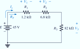
For the series configuration in Fig. 5.98, constructed using standard value resistors:
- Without making a single calculation, which resistive element will have the most voltage across it? Which will have the least?
- Which resistor will have the most impact on the total resistance and the resulting current? Find the total resistance and the current.
- Find the voltage across each element and review your response to part (a).
Expert Solution & Answer
Want to see the full answer?
Check out a sample textbook solution
Students have asked these similar questions
INSTRUCTIONS: Solve the following problems. Show and COMPLETE solutions. Draw all CIRCUIT DIAGRAMS or the equivalent circuit (dummy circuit) as the case may be. Write your solutions on sheet/s of short bond paper.
A battery is to consist of 20 identical cells. The emf of each cell is 1.5 V and the internal resistance is 0.20 ohm. This battery will be used to supply power to a 10 ohm lamp. Determine the current on the lamp if:1. The 20 cells are connected in series 2. The 20 cells are connected in parallel 3. The 20 cells are arranged 5 cells in series in 4 parallel rows.
Solve for the circuits unknowns in the picture below
In the circuit shown below, each resustor is 15 ohm, compute the equivalent resistance Req
Chapter 5 Solutions
Introductory Circuit Analysis (13th Edition)
Ch. 5 - For each configuration in Fig. 5.88, find the...Ch. 5 - For each configuration in Fig. 5.89, find the...Ch. 5 - Find the total resistance RT for each...Ch. 5 - Find the total resistance RT for each...Ch. 5 - For each circuit board in Fig. 5.92, �nd the...Ch. 5 - For the circuit in Fig. 5.93, composed of standard...Ch. 5 - For each configuration in Fig. 5.94, determine the...Ch. 5 - Find the resistance R, given the ohmmeter reading...Ch. 5 - What is the ohmmeter reading for each...Ch. 5 - For the series configuration in Fig. 5.97,...
Ch. 5 - For the series configuration in Fig. 5.98,...Ch. 5 - Find the applied voltage necessary to develop the...Ch. 5 - For each network in Fig. 5.100, constructed of...Ch. 5 - For each configuration in Fig. 5.101, what are the...Ch. 5 - For each configuration of Fig. 5.102, find the...Ch. 5 - For the circuit in Fig. 5.103, constructed of...Ch. 5 - Find the unknown quantities for the circuit of...Ch. 5 - Find the unknown quantities for the circuit in...Ch. 5 - Eight holiday lights are connected in series as...Ch. 5 - For the conditions specified in Fig. 5.107,...Ch. 5 - Combine the series voltage sources in Fig. 5.108,...Ch. 5 - Determine the current I and its direction for each...Ch. 5 - Find {he unknown voltage source and resistor for...Ch. 5 - Using Kirchhoffs voltage law, find the unknown...Ch. 5 - Find the current I for the network of Fig. 5.112....Ch. 5 - Using Kirchhoffs voltage law, determine the...Ch. 5 - Using Kirchhoffs voltage law, find the unknown...Ch. 5 - Determine the values of the unknown resistors in...Ch. 5 - For the configuration in Fig. 5.116, with standard...Ch. 5 - Using the voltage divider rule, find the indicated...Ch. 5 - Using the voltage divider rule or Kirchhoffs...Ch. 5 - Using the voltage divider rule or Kirchhoffs...Ch. 5 - Using the information provided, find the unknown...Ch. 5 - Using the voltage divider rule, �nd the unknown...Ch. 5 - Design a voltage divider circuit that will permit...Ch. 5 - Design the voltage divider in Fig. 5.122 such that...Ch. 5 - Find the voltage across each resistor in Fig....Ch. 5 - Design the circuit in Fig. 5.124 such that...Ch. 5 - Determine the voltages Va,Vb, and Vab for the...Ch. 5 - Determine the current I (with direction) and the...Ch. 5 - For the network in Fig. 5.127 determine the...Ch. 5 - Given the information appearing in Fig. 5.128,...Ch. 5 - Determine the values of R1,R2,R3, and R4 for the...Ch. 5 - For the network in Fig. 5.130, determine the...Ch. 5 - For the integrated circuit in Fig. 5.131,...Ch. 5 - For the integrated circuit in Fig. 5.132,...Ch. 5 - Find the internal resistance of a battery that has...Ch. 5 - Find the voltage to the load (full-and conditions)...Ch. 5 - Determine the current through the circuit in Fig....Ch. 5 - Use the computer to verify the results of Example...Ch. 5 - Use the computer to verify the results of Example...Ch. 5 - Use the computer to verify the results of Example...
Additional Engineering Textbook Solutions
Find more solutions based on key concepts
Design an ideal inverting op-amp circuit such that the voltage gain is Av=25 . The maximum current in any resis...
Microelectronics: Circuit Analysis and Design
Identify the type of input and output configuration for each diff-amp in Figure 18-35.
Electronics Fundamentals: Circuits, Devices & Applications
For the “tank” circuit in Fig. 14.79, find the resonant frequency.
Figure 14.79
For Probs. 14.39, 14.71, and 1...
Fundamentals of Electric Circuits
What is the color code for a 365- five-band precision resistor with a tolerance of 5 percent?
ELECTRICITY FOR TRADES (LOOSELEAF)
Electric power systems provide energy in a variety of commercial and industrial settings. Make a list of system...
Principles and Applications of Electrical Engineering
Does the severity of an electric shock increase ordecrease with eh of the following changes? a. A decrease in t...
Electric Motors and Control Systems
Knowledge Booster


Learn more about
Need a deep-dive on the concept behind this application? Look no further. Learn more about this topic, electrical-engineering and related others by exploring similar questions and additional content below.Similar questions
- Show and COMPLETE solutions. Draw all CIRCUIT DIAGRAMS or the equivalent circuit (dummy circuit) as the case may be. A battery is to consist of 20 identical cells. The emf of each cell is 1.5 V and the internal resistance is 0.20 ohm. This battery will be used to supply power to a 10-ohm lamp. Determine thecurrent on the lamp if: The 20 cells are arranged 5 cells in series in 4 parallel rows.arrow_forwardUsing superposition, determine the current through the inductance XL for each network in the figurearrow_forwardIn an electrical circuit four resistors are connected in parallel and their equivalent resistance is 50ohms. Find the value of each resistors if the currents through each impedance are 0.8, 0.4, 0.6 and 0.2 ampere.arrow_forward
- 5. Solve with illustration Solve for the required parameter Make sure to add the solutionarrow_forwardWhich of the following is/are an accurate statement/s? A The potential in any closed loop is zero. B In parallel connection of two resistors, the current is higher for lower resistance. The voltage divider is used to find the potential across the resistors in parallel. The sum of current entering the junction is equal to the sum of potential in any closed loop.arrow_forward1a. Calculate the equivalent resistance of R4 and R5 1b. Adding the values of resistor R1 and R2 to R equivalent. Calculate the circuit resistance seen by the power source. 2a. Measure the total resistance across terminals A and D, using ohmmeter function of the electronic VOM. Make sure that switch S1 is in the open position. Measured Total Resistance in Multisim= 4.15kohms 2b. Does the measured total resistance agree exactly with your calculated resistance? Explainarrow_forward
- The lead storage batteries "A" and "B" are connected in parallel. "A" hasan open circuit voltage of 12 V and an internal resistance of 0.2 ohm.Battery "B" has an open circuit voltage of 12.2 V and an internalresistance of 0.3 ohm. If the two batteries together deliver power to a0.5-ohm power resistor. Neglecting effects of temperature, how muchcurrent is contributed by battery "A"?arrow_forwardFinding V5 and I5. (Voltage and current )arrow_forwardDraw a schematic of a circuit that converts the thermistor resistance to a measurable voltage. I suggest basing it on the only circuit you have studied so far: the voltage divider. Assuming that you have a negative-thermal coecient (NTC) thermistor and that you want higher temperature to result in higher voltage, which of the resistors in a voltage divider is the thermistor and which is a fixed resistor? Use the proper thermistor symbol and put the thermistor part number on the schematic. (For the final report, update this schematic with the resistor value chosen in the lab.)arrow_forward
- 1. a) Design a combination circuit that has four LED’s and one resistor. Each LED will be in parallel and have its own switch. The circuit will have a resistor in series with the LED’s while they are connected in parallel. Each LED’s will drop 1.4vDC in parallel, with the same specifications. Make sure you size R1 (resistor R1) correctly using a VT of 9v. Each LED branch will have 20mA of current through it. Calculate all values including power at each component. b) Also, if the 9v battery had a rating of 2 watt-hours, how long would it last? If you wanted to make each LED 1/3 brighter than the other in parallel, how would you change the circuit to make that happen? Explain and show calculations. (Hint… you do not need transistor(s), but you can use them in your design).arrow_forwardexample (H.w): A Current has an internal resistance of 782 ed to measure the Current through Rc in the below is used creuit. Find the percentuge error of the reading due to Ammeter hocaeding. Razike Rbzikuz AAmmeterarrow_forwardFind the total resistance of the CKT Consider R = 1ohmarrow_forward
arrow_back_ios
SEE MORE QUESTIONS
arrow_forward_ios
Recommended textbooks for you
 Introductory Circuit Analysis (13th Edition)Electrical EngineeringISBN:9780133923605Author:Robert L. BoylestadPublisher:PEARSON
 Delmar's Standard Textbook Of ElectricityElectrical EngineeringISBN:9781337900348Author:Stephen L. HermanPublisher:Cengage Learning
 Programmable Logic ControllersElectrical EngineeringISBN:9780073373843Author:Frank D. PetruzellaPublisher:McGraw-Hill Education
 Fundamentals of Electric CircuitsElectrical EngineeringISBN:9780078028229Author:Charles K Alexander, Matthew SadikuPublisher:McGraw-Hill Education
 Electric Circuits. (11th Edition)Electrical EngineeringISBN:9780134746968Author:James W. Nilsson, Susan RiedelPublisher:PEARSON
 Engineering ElectromagneticsElectrical EngineeringISBN:9780078028151Author:Hayt, William H. (william Hart), Jr, BUCK, John A.Publisher:Mcgraw-hill Education,
Introductory Circuit Analysis (13th Edition)
Electrical Engineering
ISBN:9780133923605
Author:Robert L. Boylestad
Publisher:PEARSON
Delmar's Standard Textbook Of Electricity
Electrical Engineering
ISBN:9781337900348
Author:Stephen L. Herman
Publisher:Cengage Learning
Programmable Logic Controllers
Electrical Engineering
ISBN:9780073373843
Author:Frank D. Petruzella
Publisher:McGraw-Hill Education
Fundamentals of Electric Circuits
Electrical Engineering
ISBN:9780078028229
Author:Charles K Alexander, Matthew Sadiku
Publisher:McGraw-Hill Education
Electric Circuits. (11th Edition)
Electrical Engineering
ISBN:9780134746968
Author:James W. Nilsson, Susan Riedel
Publisher:PEARSON
Engineering Electromagnetics
Electrical Engineering
ISBN:9780078028151
Author:Hayt, William H. (william Hart), Jr, BUCK, John A.
Publisher:Mcgraw-hill Education,
Kirchhoff's Rules of Electrical Circuits; Author: Flipping Physics;https://www.youtube.com/watch?v=d0O-KUKP4nM;License: Standard YouTube License, CC-BY