
Introductory Circuit Analysis (13th Edition)
13th Edition
ISBN: 9780133923605
Author: Robert L. Boylestad
Publisher: PEARSON
expand_more
expand_more
format_list_bulleted
Concept explainers
Videos
Textbook Question
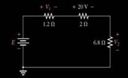
Chapter 5, Problem 31P
Using the voltage divider rule or Kirchhoff’s voltage law, determine the unknown voltages for the configurations in Fig. 5.118. Do not calculate the current!
Expert Solution & Answer
Want to see the full answer?
Check out a sample textbook solution
Students have asked these similar questions
*27. For the network of Fig. 5.96, determine the voltages:
a. V V. Ve, Va, v.
b. Vab. Vae Veb
c. Va, V
47 V
2 kfn
3 kN
20 V
4 kfl
FIG. 5.96
Heaw: tind Vab in the network in fig
1)5A
62
c.
9.
Vab
Vab--5.83U
ansi
1) In the Fig. 5 – 4, between points A and B, which branch of the circuit has the greatest current flow if all resistors have the exact values indicated?a. R2, R3.b. R4c. R5d. All branch currents are the same value.
2) Which of the following would be a true statement if resistor R7 became short circuited in Fig. 5 – 4.a. Current flow would decrease.b. Voltage E AB would decrease.c. Voltage E CD would increase.d. Current flow would increase.
6. Which of the following would be a false statement if resistor R7 opened in Fig. 5 – 4?a. Current flow would decrease.b. Voltage E AB would decrease.c. Voltage E CD would increase.d. None of the above.
Chapter 5 Solutions
Introductory Circuit Analysis (13th Edition)
Ch. 5 - For each configuration in Fig. 5.88, find the...Ch. 5 - For each configuration in Fig. 5.89, find the...Ch. 5 - Find the total resistance RT for each...Ch. 5 - Find the total resistance RT for each...Ch. 5 - For each circuit board in Fig. 5.92, �nd the...Ch. 5 - For the circuit in Fig. 5.93, composed of standard...Ch. 5 - For each configuration in Fig. 5.94, determine the...Ch. 5 - Find the resistance R, given the ohmmeter reading...Ch. 5 - What is the ohmmeter reading for each...Ch. 5 - For the series configuration in Fig. 5.97,...
Ch. 5 - For the series configuration in Fig. 5.98,...Ch. 5 - Find the applied voltage necessary to develop the...Ch. 5 - For each network in Fig. 5.100, constructed of...Ch. 5 - For each configuration in Fig. 5.101, what are the...Ch. 5 - For each configuration of Fig. 5.102, find the...Ch. 5 - For the circuit in Fig. 5.103, constructed of...Ch. 5 - Find the unknown quantities for the circuit of...Ch. 5 - Find the unknown quantities for the circuit in...Ch. 5 - Eight holiday lights are connected in series as...Ch. 5 - For the conditions specified in Fig. 5.107,...Ch. 5 - Combine the series voltage sources in Fig. 5.108,...Ch. 5 - Determine the current I and its direction for each...Ch. 5 - Find {he unknown voltage source and resistor for...Ch. 5 - Using Kirchhoffs voltage law, find the unknown...Ch. 5 - Find the current I for the network of Fig. 5.112....Ch. 5 - Using Kirchhoffs voltage law, determine the...Ch. 5 - Using Kirchhoffs voltage law, find the unknown...Ch. 5 - Determine the values of the unknown resistors in...Ch. 5 - For the configuration in Fig. 5.116, with standard...Ch. 5 - Using the voltage divider rule, find the indicated...Ch. 5 - Using the voltage divider rule or Kirchhoffs...Ch. 5 - Using the voltage divider rule or Kirchhoffs...Ch. 5 - Using the information provided, find the unknown...Ch. 5 - Using the voltage divider rule, �nd the unknown...Ch. 5 - Design a voltage divider circuit that will permit...Ch. 5 - Design the voltage divider in Fig. 5.122 such that...Ch. 5 - Find the voltage across each resistor in Fig....Ch. 5 - Design the circuit in Fig. 5.124 such that...Ch. 5 - Determine the voltages Va,Vb, and Vab for the...Ch. 5 - Determine the current I (with direction) and the...Ch. 5 - For the network in Fig. 5.127 determine the...Ch. 5 - Given the information appearing in Fig. 5.128,...Ch. 5 - Determine the values of R1,R2,R3, and R4 for the...Ch. 5 - For the network in Fig. 5.130, determine the...Ch. 5 - For the integrated circuit in Fig. 5.131,...Ch. 5 - For the integrated circuit in Fig. 5.132,...Ch. 5 - Find the internal resistance of a battery that has...Ch. 5 - Find the voltage to the load (full-and conditions)...Ch. 5 - Determine the current through the circuit in Fig....Ch. 5 - Use the computer to verify the results of Example...Ch. 5 - Use the computer to verify the results of Example...Ch. 5 - Use the computer to verify the results of Example...
Additional Engineering Textbook Solutions
Find more solutions based on key concepts
How many coulombs do 93.8 1016 electrons represent?
Principles Of Electric Circuits
For the “tank” circuit in Fig. 14.79, find the resonant frequency.
Figure 14.79
For Probs. 14.39, 14.71, and 1...
Fundamentals of Electric Circuits
Assume a telephone signal travels through a cable at two-thirds the speed of light. How long does it take the s...
Electric Circuits (10th Edition)
Find I0 and I1 in the circuit in Fig.P2.12.
Basic Engineering Circuit Analysis
Electric power systems provide energy in a variety of commercial and industrial settings. Make a list of system...
Principles and Applications of Electrical Engineering
Three point charges of equal magnitude q, that will yield a zero net electric field at the origin.
Engineering Electromagnetics
Knowledge Booster


Learn more about
Need a deep-dive on the concept behind this application? Look no further. Learn more about this topic, electrical-engineering and related others by exploring similar questions and additional content below.Similar questions
- PROBLEMS nl 167 For the network of Fig. 5.97, determine the voltages: 1. I, V, Ve Va b. Fa Vet Ved c. Vat l'e 2 kn 44 V 4 kfl 20 V 6 kn FIG. 5.97 Problem 28.arrow_forwardFrom Fig. 5.4 which resistors consumes the least power?arrow_forward5.) When a resistance of 3 ohms is placed across the terminals of battery, the current is 2A. When the resistance is increased to 42 ohms, the current falls to 1 A. Find emf of battery and its internal resistance.arrow_forward
- *26. For the network of Fig. 5.164: a. Calculate Ig and Ic. b. Determine re. c. Determine Z; and Zo. d. Find Ay. Vcc= 20 V 12 V 56 k2 B = 120 o= 40 k2 B= 200 Sos = 20 uS 390 k2 8.2 ΚΩ 5.6 k2 2 k2 Zo -8 V FIG. 5.163 FIG. 5.164 Problem 25. Problem 26.arrow_forward5.32 Calculate i, and vo in the circuit Find the power dissipated by the 60-k resistor. 4 m V +1 www. + RF ww 50 km2 R1 10 km2 ANS: Ix = 0.6 μA; PR3= 2.4 nW Ix 20 kQ2 www R2 60 km2 R3 wwww 30 kQ2 R4 wwarrow_forwardEXAMPLE 14 For the parallel network in Fig. 6 a. Without making a single calculation, make a guess on the total resistance. b. Calculate the total resistance and compare it to your guess in part (a). c. Without making a single calculation, which branch will have the most current? Which will have the least? d. Calculate the current through each branch, and compare your results to the assumptions of part (c). e. Find the source current and test whether it equals the sum of the branch currents. f. How does the magnitude of the source current compare to that of the branch currents? RT 10 kn R 22 kn R, 1.2 kn R 56 kflarrow_forward
- FIG. 5.96 Problem 27 POBLEMS 167 Fer the network of Fig. 5.97, determine the voltages: A l'a la 44 V FIG. 5.97 Probiem 28. IIarrow_forward5. Manufacturers recommend always powering devices using batteries of the same brand and freshness. This is important. Batteries change voltage as they discharge, which can cause old batteries to drag down new ones. To illustrate this, consider the circuit shown below. Show that when the load is connected, most of the current that leaves the new battery does not go through the load. IntRes2 200mQ DeadChemistry 1.1V Old Battery IntRes1 100mQ FreshChemistry 1.5V NewBattery Off Von LoadCircuits 1000arrow_forward5-A) Justify the reason, why the true value of a circuit is suddenly changed into a reduced measured value in a meter while measuring the true value. Mention how it will affect the measurement in the ammeter with necessary drawings. Also, how to reduce the effectarrow_forward
- Q5. Two same size PV Modules are connected in Parallel. The specification of each module is given as, Number of cells = 39, Area of each cell is 10 cm x 10 cm, the insolation value is 900 W/m?, take efficiency of module as 12%. Calculate the following for the above PV Panel. A. Total Output Voltage B. Total Current Output D. Total Power Outputarrow_forwardCompute the total resistance.arrow_forwardExplain the importance and use of the voltage and current divider... Explained and discuss the observation in voltage and current divider...Atleast 300-400 words... Thank you for your help... Your help and effor is greatly appreciated Thank you so much...arrow_forward
arrow_back_ios
SEE MORE QUESTIONS
arrow_forward_ios
Recommended textbooks for you
 Introductory Circuit Analysis (13th Edition)Electrical EngineeringISBN:9780133923605Author:Robert L. BoylestadPublisher:PEARSON
 Delmar's Standard Textbook Of ElectricityElectrical EngineeringISBN:9781337900348Author:Stephen L. HermanPublisher:Cengage Learning
 Programmable Logic ControllersElectrical EngineeringISBN:9780073373843Author:Frank D. PetruzellaPublisher:McGraw-Hill Education
 Fundamentals of Electric CircuitsElectrical EngineeringISBN:9780078028229Author:Charles K Alexander, Matthew SadikuPublisher:McGraw-Hill Education
 Electric Circuits. (11th Edition)Electrical EngineeringISBN:9780134746968Author:James W. Nilsson, Susan RiedelPublisher:PEARSON
 Engineering ElectromagneticsElectrical EngineeringISBN:9780078028151Author:Hayt, William H. (william Hart), Jr, BUCK, John A.Publisher:Mcgraw-hill Education,
Introductory Circuit Analysis (13th Edition)
Electrical Engineering
ISBN:9780133923605
Author:Robert L. Boylestad
Publisher:PEARSON
Delmar's Standard Textbook Of Electricity
Electrical Engineering
ISBN:9781337900348
Author:Stephen L. Herman
Publisher:Cengage Learning
Programmable Logic Controllers
Electrical Engineering
ISBN:9780073373843
Author:Frank D. Petruzella
Publisher:McGraw-Hill Education
Fundamentals of Electric Circuits
Electrical Engineering
ISBN:9780078028229
Author:Charles K Alexander, Matthew Sadiku
Publisher:McGraw-Hill Education
Electric Circuits. (11th Edition)
Electrical Engineering
ISBN:9780134746968
Author:James W. Nilsson, Susan Riedel
Publisher:PEARSON
Engineering Electromagnetics
Electrical Engineering
ISBN:9780078028151
Author:Hayt, William H. (william Hart), Jr, BUCK, John A.
Publisher:Mcgraw-hill Education,
Kirchhoff's Rules of Electrical Circuits; Author: Flipping Physics;https://www.youtube.com/watch?v=d0O-KUKP4nM;License: Standard YouTube License, CC-BY