
Introductory Circuit Analysis (13th Edition)
13th Edition
ISBN: 9780133923605
Author: Robert L. Boylestad
Publisher: PEARSON
expand_more
expand_more
format_list_bulleted
Concept explainers
Videos
Textbook Question
Chapter 5, Problem 2P
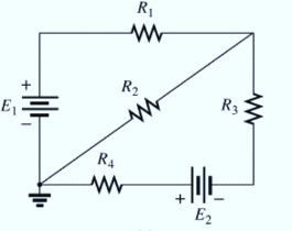
For each configuration in Fig. 5.89, find the individual (not combinations of) elements (voltage sources and/or resistors) that are ‘m series.
Expert Solution & Answer
Want to see the full answer?
Check out a sample textbook solution
Students have asked these similar questions
The 5A current Source is delivering 100w, and the 40V source is delivering 500W.
a)Determine the value of resistor R.
b)Is component X absorbing power or delviering power? How much?
Draw a schematic of a circuit that converts the thermistor resistance to a measurable voltage.
I suggest basing it on the only circuit you have studied so far: the voltage divider.
Assuming that you have a negative-thermal coecient (NTC) thermistor and that you want
higher temperature to result in higher voltage, which of the resistors in a voltage divider is
the thermistor and which is a fixed resistor?
Use the proper thermistor symbol and put the thermistor part number on the schematic.
(For the final report, update this schematic with the resistor value chosen in the lab.)
For the voltage-divider configuration of the figure below:
Sketch the DC equivalent circuit
Determine IDQ and VDSQ
Determine VD and VS
Show the details of your work.
Chapter 5 Solutions
Introductory Circuit Analysis (13th Edition)
Ch. 5 - For each configuration in Fig. 5.88, find the...Ch. 5 - For each configuration in Fig. 5.89, find the...Ch. 5 - Find the total resistance RT for each...Ch. 5 - Find the total resistance RT for each...Ch. 5 - For each circuit board in Fig. 5.92, �nd the...Ch. 5 - For the circuit in Fig. 5.93, composed of standard...Ch. 5 - For each configuration in Fig. 5.94, determine the...Ch. 5 - Find the resistance R, given the ohmmeter reading...Ch. 5 - What is the ohmmeter reading for each...Ch. 5 - For the series configuration in Fig. 5.97,...
Ch. 5 - For the series configuration in Fig. 5.98,...Ch. 5 - Find the applied voltage necessary to develop the...Ch. 5 - For each network in Fig. 5.100, constructed of...Ch. 5 - For each configuration in Fig. 5.101, what are the...Ch. 5 - For each configuration of Fig. 5.102, find the...Ch. 5 - For the circuit in Fig. 5.103, constructed of...Ch. 5 - Find the unknown quantities for the circuit of...Ch. 5 - Find the unknown quantities for the circuit in...Ch. 5 - Eight holiday lights are connected in series as...Ch. 5 - For the conditions specified in Fig. 5.107,...Ch. 5 - Combine the series voltage sources in Fig. 5.108,...Ch. 5 - Determine the current I and its direction for each...Ch. 5 - Find {he unknown voltage source and resistor for...Ch. 5 - Using Kirchhoffs voltage law, find the unknown...Ch. 5 - Find the current I for the network of Fig. 5.112....Ch. 5 - Using Kirchhoffs voltage law, determine the...Ch. 5 - Using Kirchhoffs voltage law, find the unknown...Ch. 5 - Determine the values of the unknown resistors in...Ch. 5 - For the configuration in Fig. 5.116, with standard...Ch. 5 - Using the voltage divider rule, find the indicated...Ch. 5 - Using the voltage divider rule or Kirchhoffs...Ch. 5 - Using the voltage divider rule or Kirchhoffs...Ch. 5 - Using the information provided, find the unknown...Ch. 5 - Using the voltage divider rule, �nd the unknown...Ch. 5 - Design a voltage divider circuit that will permit...Ch. 5 - Design the voltage divider in Fig. 5.122 such that...Ch. 5 - Find the voltage across each resistor in Fig....Ch. 5 - Design the circuit in Fig. 5.124 such that...Ch. 5 - Determine the voltages Va,Vb, and Vab for the...Ch. 5 - Determine the current I (with direction) and the...Ch. 5 - For the network in Fig. 5.127 determine the...Ch. 5 - Given the information appearing in Fig. 5.128,...Ch. 5 - Determine the values of R1,R2,R3, and R4 for the...Ch. 5 - For the network in Fig. 5.130, determine the...Ch. 5 - For the integrated circuit in Fig. 5.131,...Ch. 5 - For the integrated circuit in Fig. 5.132,...Ch. 5 - Find the internal resistance of a battery that has...Ch. 5 - Find the voltage to the load (full-and conditions)...Ch. 5 - Determine the current through the circuit in Fig....Ch. 5 - Use the computer to verify the results of Example...Ch. 5 - Use the computer to verify the results of Example...Ch. 5 - Use the computer to verify the results of Example...
Additional Engineering Textbook Solutions
Find more solutions based on key concepts
Assume a telephone signal travels through a cable at two-thirds the speed of light. How long does it take the s...
Electric Circuits (10th Edition)
Find I0 and I1 in the circuit in Fig.P2.12.
Basic Engineering Circuit Analysis
The voltage source of the circuit shown in Fig. P1.29 is given by s(t)=25cos(4104t45)(V). Obtain an expression ...
Fundamentals of Applied Electromagnetics (7th Edition)
For the “tank” circuit in Fig. 14.79, find the resonant frequency.
Figure 14.79
For Probs. 14.39, 14.71, and 1...
Fundamentals of Electric Circuits
Analog Voltmeter Design Figure P2-98(a) shows a voltmeter circuit consisting of a D'Arsonval meter, two series ...
ANALYSIS+DESIGN OF LINEAR CIRCUITS(LL)
Electric power systems provide energy in a variety of commercial and industrial settings. Make a list of system...
Principles and Applications of Electrical Engineering
Knowledge Booster


Learn more about
Need a deep-dive on the concept behind this application? Look no further. Learn more about this topic, electrical-engineering and related others by exploring similar questions and additional content below.Similar questions
- At what height are the telephone outlets in this residence mounted? Give measurement to center. _____arrow_forwardFor the voltage-divider configuration of the figure below: Show the details of your work. Sketch the DC equivalent circuit Determine and Determine andarrow_forwardWHEN COMBINING RESISTORS IN SERIES, THE TOTAL COMBINED RESISTANCE WILL BE EQUAL TO O A. THE SUM OF ALL THE RECIPROCALS OF EACH INDIVIDUAL RESISTANCE IN SERIES. O B. THE SUM OF ALL THE RESISTANCES IN SERIES. O C. THE PRODUCT OF ALL THE RESISTANCES IN SERIES. O D. THE RECIPROCAL OF THE SUM OF RECIPROCALS OF EACH INDIVIDUAL RESISTANCE IN SERIES.arrow_forward
- A 0 – 150 voltmeter has a resistance of 2000-ohms per volt. It is desired to change this voltmeter to a 0 – 600 volt instrument by the edition of an external multiplier. What is the resistance, in ohms, of this external multiplier?arrow_forwardINSTRUCTIONS: Solve the following problems. Show and COMPLETE solutions. Draw all CIRCUIT DIAGRAMS or the equivalent circuit (dummy circuit) as the case may be. Write your solutions on sheet/s of short bond paper. A battery is to consist of 20 identical cells. The emf of each cell is 1.5 V and the internal resistance is 0.20 ohm. This battery will be used to supply power to a 10 ohm lamp. Determine the current on the lamp if:1. The 20 cells are connected in series 2. The 20 cells are connected in parallel 3. The 20 cells are arranged 5 cells in series in 4 parallel rows.arrow_forwardShunt PMMC was designed by using indirect method to provide an ammeter with current range 5A, 10A, 20A. The internal resistance is 500 and full scale current of 1mA, find Rb.arrow_forward
- Q5:- Using the information provided in cct, determine the current through each branch using simply the ratio of parallel resistor values. Then determine the total current IT 10 0 www R 13 A 20 V 25 01 60arrow_forwardQ1: Determine the levels of ICQ and VCEQ for the voltage-divider configuration of Figure below, using the exact and approximate techniques and compare solutions. (50 degree) 18 V 5.6ka 82k i1 10 uF Vero B-50 10 uF 22ka 1.2kaarrow_forwardcan you please explain how we do the d) sectionarrow_forward
arrow_back_ios
SEE MORE QUESTIONS
arrow_forward_ios
Recommended textbooks for you
 EBK ELECTRICAL WIRING RESIDENTIALElectrical EngineeringISBN:9781337516549Author:SimmonsPublisher:CENGAGE LEARNING - CONSIGNMENT
EBK ELECTRICAL WIRING RESIDENTIAL
Electrical Engineering
ISBN:9781337516549
Author:Simmons
Publisher:CENGAGE LEARNING - CONSIGNMENT
Current Divider Rule; Author: Neso Academy;https://www.youtube.com/watch?v=hRU1mKWUehY;License: Standard YouTube License, CC-BY