
Introductory Circuit Analysis (13th Edition)
13th Edition
ISBN: 9780133923605
Author: Robert L. Boylestad
Publisher: PEARSON
expand_more
expand_more
format_list_bulleted
Concept explainers
Videos
Textbook Question
Chapter 5, Problem 37P
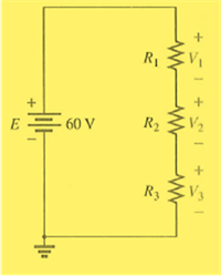
Find the voltage across each resistor in Fig. 5.123 if
Expert Solution & Answer
Want to see the full answer?
Check out a sample textbook solution
Students have asked these similar questions
5.52
What resistor connected between terminals a and h in the bridgc circuit shown in Fig. 5-53 absorbs maximum
power and what is this power!
Ans.
2.67 kN, 4.25 mW
2 kll
73.3 kfl
20 V
5 kn
2 kn
Fig. 5-53
Determine V, for the network of the figure below
5V
5V
Ge
22 k
Three cells each having emf of 1.4 V and internal resistance of 0.75 Ω are connected in parallel to a resistance of 2 Ω. Find the total current. Express in four decimal places.
Chapter 5 Solutions
Introductory Circuit Analysis (13th Edition)
Ch. 5 - For each configuration in Fig. 5.88, find the...Ch. 5 - For each configuration in Fig. 5.89, find the...Ch. 5 - Find the total resistance RT for each...Ch. 5 - Find the total resistance RT for each...Ch. 5 - For each circuit board in Fig. 5.92, �nd the...Ch. 5 - For the circuit in Fig. 5.93, composed of standard...Ch. 5 - For each configuration in Fig. 5.94, determine the...Ch. 5 - Find the resistance R, given the ohmmeter reading...Ch. 5 - What is the ohmmeter reading for each...Ch. 5 - For the series configuration in Fig. 5.97,...
Ch. 5 - For the series configuration in Fig. 5.98,...Ch. 5 - Find the applied voltage necessary to develop the...Ch. 5 - For each network in Fig. 5.100, constructed of...Ch. 5 - For each configuration in Fig. 5.101, what are the...Ch. 5 - For each configuration of Fig. 5.102, find the...Ch. 5 - For the circuit in Fig. 5.103, constructed of...Ch. 5 - Find the unknown quantities for the circuit of...Ch. 5 - Find the unknown quantities for the circuit in...Ch. 5 - Eight holiday lights are connected in series as...Ch. 5 - For the conditions specified in Fig. 5.107,...Ch. 5 - Combine the series voltage sources in Fig. 5.108,...Ch. 5 - Determine the current I and its direction for each...Ch. 5 - Find {he unknown voltage source and resistor for...Ch. 5 - Using Kirchhoffs voltage law, find the unknown...Ch. 5 - Find the current I for the network of Fig. 5.112....Ch. 5 - Using Kirchhoffs voltage law, determine the...Ch. 5 - Using Kirchhoffs voltage law, find the unknown...Ch. 5 - Determine the values of the unknown resistors in...Ch. 5 - For the configuration in Fig. 5.116, with standard...Ch. 5 - Using the voltage divider rule, find the indicated...Ch. 5 - Using the voltage divider rule or Kirchhoffs...Ch. 5 - Using the voltage divider rule or Kirchhoffs...Ch. 5 - Using the information provided, find the unknown...Ch. 5 - Using the voltage divider rule, �nd the unknown...Ch. 5 - Design a voltage divider circuit that will permit...Ch. 5 - Design the voltage divider in Fig. 5.122 such that...Ch. 5 - Find the voltage across each resistor in Fig....Ch. 5 - Design the circuit in Fig. 5.124 such that...Ch. 5 - Determine the voltages Va,Vb, and Vab for the...Ch. 5 - Determine the current I (with direction) and the...Ch. 5 - For the network in Fig. 5.127 determine the...Ch. 5 - Given the information appearing in Fig. 5.128,...Ch. 5 - Determine the values of R1,R2,R3, and R4 for the...Ch. 5 - For the network in Fig. 5.130, determine the...Ch. 5 - For the integrated circuit in Fig. 5.131,...Ch. 5 - For the integrated circuit in Fig. 5.132,...Ch. 5 - Find the internal resistance of a battery that has...Ch. 5 - Find the voltage to the load (full-and conditions)...Ch. 5 - Determine the current through the circuit in Fig....Ch. 5 - Use the computer to verify the results of Example...Ch. 5 - Use the computer to verify the results of Example...Ch. 5 - Use the computer to verify the results of Example...
Knowledge Booster


Learn more about
Need a deep-dive on the concept behind this application? Look no further. Learn more about this topic, electrical-engineering and related others by exploring similar questions and additional content below.Similar questions
- Using the voltage divider rule or Kirchhoff's voltage law, determine the unknown voltages for the configurations in Fig. 5.119. Do not calculate the current! E₁ + 50 V + E • 3.3 ΚΩ + Vi 6.8 ΚΩ · 4.7 ΚΩ WHI • 10 ΚΩ 30 V 0 + Vx E HI 2 Ω 68 Ω 100 Ω Μ + + 1000 V - UNIVERSarrow_forwardIn the circuit of Fig. 5-55, what resistor connected across terminals a and h will absorb maximum power and what is this power? Ans. 100 k2. 62.5 W 6 kN 3 mV 0.0002V 1001 75 kn Fig. 5-55arrow_forwardExample: 5.1 Calculate the node voltages in the circuit shown in the below figure: 5 A 42 21 22 10 Aarrow_forward
- Homework: Obtain vo in the circuit of the following figure. 5.3 30 V 20 V 4 k2 2 k2 3 k2 Answer 20 V wwarrow_forward5.40 Find the Norton equivalent of the circuit of Fig. 5-43. Reference I, up. Ans. 8 Ω.8Α 40 0 80 V 30 A 10 0 1000 V Fig. 5-43arrow_forward1. Determine the maximum power delivered to the v 4 V 5Q 15 Q2 5Q 692 www Vx www Rarrow_forward
- Find the voltage across each resistor in Fig. 5.123 if R1 = 2R3 and R2 = 7R3. E + 80 V R₁ R2 R3 5+15+arrow_forward2. For the following circuit determine the total resistance, R. 300 0 200 N RT 4 k2 300 L 400 N 500 Narrow_forwardWhat is the common-mode voltage of the balanced (both voltage dividers contain two identical resistances) Wheatstone bridge in Fig. 1?arrow_forward
- Give the total voltage for the circuit below: 5V 3V Select one: 1V barrow_forwardDetermine ID and Vo. For your final answer just write the values example: 1mA,1Varrow_forwardFind the total resistance R, for each configuration in Fig. 5.86. Note that only standard resistor values were used. R R3 R3 R 0.39 kn 12 kn 1.20 2.7A RT R, (a) (b) R 82 kl 47A R 10kn R, {1 kn R4 Ry 1.8 n R.4, 820n R R, 12 kl 91 0 27 kn (c) (d) FIG. 5.86arrow_forward
arrow_back_ios
SEE MORE QUESTIONS
arrow_forward_ios
Recommended textbooks for you
 Introductory Circuit Analysis (13th Edition)Electrical EngineeringISBN:9780133923605Author:Robert L. BoylestadPublisher:PEARSON
 Delmar's Standard Textbook Of ElectricityElectrical EngineeringISBN:9781337900348Author:Stephen L. HermanPublisher:Cengage Learning
 Programmable Logic ControllersElectrical EngineeringISBN:9780073373843Author:Frank D. PetruzellaPublisher:McGraw-Hill Education
 Fundamentals of Electric CircuitsElectrical EngineeringISBN:9780078028229Author:Charles K Alexander, Matthew SadikuPublisher:McGraw-Hill Education
 Electric Circuits. (11th Edition)Electrical EngineeringISBN:9780134746968Author:James W. Nilsson, Susan RiedelPublisher:PEARSON
 Engineering ElectromagneticsElectrical EngineeringISBN:9780078028151Author:Hayt, William H. (william Hart), Jr, BUCK, John A.Publisher:Mcgraw-hill Education,
Introductory Circuit Analysis (13th Edition)
Electrical Engineering
ISBN:9780133923605
Author:Robert L. Boylestad
Publisher:PEARSON
Delmar's Standard Textbook Of Electricity
Electrical Engineering
ISBN:9781337900348
Author:Stephen L. Herman
Publisher:Cengage Learning
Programmable Logic Controllers
Electrical Engineering
ISBN:9780073373843
Author:Frank D. Petruzella
Publisher:McGraw-Hill Education
Fundamentals of Electric Circuits
Electrical Engineering
ISBN:9780078028229
Author:Charles K Alexander, Matthew Sadiku
Publisher:McGraw-Hill Education
Electric Circuits. (11th Edition)
Electrical Engineering
ISBN:9780134746968
Author:James W. Nilsson, Susan Riedel
Publisher:PEARSON
Engineering Electromagnetics
Electrical Engineering
ISBN:9780078028151
Author:Hayt, William H. (william Hart), Jr, BUCK, John A.
Publisher:Mcgraw-hill Education,
Kirchhoff's Rules of Electrical Circuits; Author: Flipping Physics;https://www.youtube.com/watch?v=d0O-KUKP4nM;License: Standard YouTube License, CC-BY