
Introductory Circuit Analysis (13th Edition)
13th Edition
ISBN: 9780133923605
Author: Robert L. Boylestad
Publisher: PEARSON
expand_more
expand_more
format_list_bulleted
Concept explainers
Videos
Textbook Question
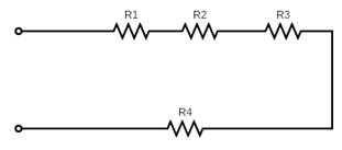
Chapter 5, Problem 3P
Find the total resistance
Expert Solution & Answer
Want to see the full answer?
Check out a sample textbook solution
Students have asked these similar questions
What is the relevance of safety factors in circuit design? Explain in a paragraph with 8 sentences.
Include an illustration of the circuit in the solutions. Thank you
From Fig. 5.4 which resistors consumes the least power?
Chapter 5 Solutions
Introductory Circuit Analysis (13th Edition)
Ch. 5 - For each configuration in Fig. 5.88, find the...Ch. 5 - For each configuration in Fig. 5.89, find the...Ch. 5 - Find the total resistance RT for each...Ch. 5 - Find the total resistance RT for each...Ch. 5 - For each circuit board in Fig. 5.92, �nd the...Ch. 5 - For the circuit in Fig. 5.93, composed of standard...Ch. 5 - For each configuration in Fig. 5.94, determine the...Ch. 5 - Find the resistance R, given the ohmmeter reading...Ch. 5 - What is the ohmmeter reading for each...Ch. 5 - For the series configuration in Fig. 5.97,...
Ch. 5 - For the series configuration in Fig. 5.98,...Ch. 5 - Find the applied voltage necessary to develop the...Ch. 5 - For each network in Fig. 5.100, constructed of...Ch. 5 - For each configuration in Fig. 5.101, what are the...Ch. 5 - For each configuration of Fig. 5.102, find the...Ch. 5 - For the circuit in Fig. 5.103, constructed of...Ch. 5 - Find the unknown quantities for the circuit of...Ch. 5 - Find the unknown quantities for the circuit in...Ch. 5 - Eight holiday lights are connected in series as...Ch. 5 - For the conditions specified in Fig. 5.107,...Ch. 5 - Combine the series voltage sources in Fig. 5.108,...Ch. 5 - Determine the current I and its direction for each...Ch. 5 - Find {he unknown voltage source and resistor for...Ch. 5 - Using Kirchhoffs voltage law, find the unknown...Ch. 5 - Find the current I for the network of Fig. 5.112....Ch. 5 - Using Kirchhoffs voltage law, determine the...Ch. 5 - Using Kirchhoffs voltage law, find the unknown...Ch. 5 - Determine the values of the unknown resistors in...Ch. 5 - For the configuration in Fig. 5.116, with standard...Ch. 5 - Using the voltage divider rule, find the indicated...Ch. 5 - Using the voltage divider rule or Kirchhoffs...Ch. 5 - Using the voltage divider rule or Kirchhoffs...Ch. 5 - Using the information provided, find the unknown...Ch. 5 - Using the voltage divider rule, �nd the unknown...Ch. 5 - Design a voltage divider circuit that will permit...Ch. 5 - Design the voltage divider in Fig. 5.122 such that...Ch. 5 - Find the voltage across each resistor in Fig....Ch. 5 - Design the circuit in Fig. 5.124 such that...Ch. 5 - Determine the voltages Va,Vb, and Vab for the...Ch. 5 - Determine the current I (with direction) and the...Ch. 5 - For the network in Fig. 5.127 determine the...Ch. 5 - Given the information appearing in Fig. 5.128,...Ch. 5 - Determine the values of R1,R2,R3, and R4 for the...Ch. 5 - For the network in Fig. 5.130, determine the...Ch. 5 - For the integrated circuit in Fig. 5.131,...Ch. 5 - For the integrated circuit in Fig. 5.132,...Ch. 5 - Find the internal resistance of a battery that has...Ch. 5 - Find the voltage to the load (full-and conditions)...Ch. 5 - Determine the current through the circuit in Fig....Ch. 5 - Use the computer to verify the results of Example...Ch. 5 - Use the computer to verify the results of Example...Ch. 5 - Use the computer to verify the results of Example...
Additional Engineering Textbook Solutions
Find more solutions based on key concepts
Electric power systems provide energy in a variety of commercial and industrial settings. Make a list of system...
Principles and Applications of Electrical Engineering
The voltage source of the circuit shown in Fig. P1.29 is given by s(t)=25cos(4104t45)(V). Obtain an expression ...
Fundamentals of Applied Electromagnetics (7th Edition)
Analog Voltmeter Design Figure P2-98(a) shows a voltmeter circuit consisting of a D'Arsonval meter, two series ...
ANALYSIS+DESIGN OF LINEAR CIRCUITS(LL)
For the “tank” circuit in Fig. 14.79, find the resonant frequency.
Figure 14.79
For Probs. 14.39, 14.71, and 1...
Fundamentals of Electric Circuits
Design an ideal inverting op-amp circuit such that the voltage gain is Av=25 . The maximum current in any resis...
Microelectronics: Circuit Analysis and Design
When travelers from the USA and Canada visit Europe, they encounter a different power distribution system. Wall...
Electric machinery fundamentals
Knowledge Booster


Learn more about
Need a deep-dive on the concept behind this application? Look no further. Learn more about this topic, electrical-engineering and related others by exploring similar questions and additional content below.Similar questions
- Q5/ A- A series- type ohmmeter, designed to operate with a 6V battery, has a circuit diagram as shown in figure below. The meter movement has an internal resistance of 2000 Q and requires a current of 100uA for full scale deflection the value of R1 is 49KO. a) Assuming the battery voltage has fallen to 5.9V. Calculate the value of R2 required to zero the meter. b) Under the conditions mentioned in part (a), an unknown resistor is connected to the meter causing a 60 percent meter deflection. Calculate the value of the unknown resistance. RI Rm R25 Rxarrow_forwardContext: The results shown in table 5.0 were obtained using a potentiometer on a breadboard and measured with a DMM multimeter using the Ohmmeter function. Please answer the question below including as much detail and information as possible. Thank you very much.arrow_forwardFind the value of Rv (in ohms) needed for a full-scale reading of 50 V. Find the value of Rv (in ohms) needed for a full-scale reading of 5 V. Find the value of Rv (in ohms) needed for a full-scale reading of 250 mV Find the value of Rv (in ohms) needed for a full-scale reading of 25 mV.arrow_forward
- Choose Values Of Resistance (Rc And Rs) In Kilo Ohm And Then Voltage Sources In Volt (Vcc > Ves). Find All Currents And All Voltages Rc RB VCE VCC VBBarrow_forwardThe variable resistor in the circuit attached is adjusted for maximum power transfer to R0. a) find the value of R0. b) find the maximum power that can be delivered to R0.arrow_forwardThe diagram shows the circuit used to investigate how the current varies with potential difference for an electrical component P. The circuit contains an ammeter and a voltmeter. P (1)On the diagram. label the ammgter A and the voltmeter Volteter connectel aceross te inal, Ammeter Connected in sertes to the cirevil. (ii) The position of the contact of the potential divider is moved so that the reading on the voltmeter becomes zero. Label this position Z.arrow_forward
- Problem 5.1: Calculate the voltage at V relative to ground in the following circuit. Assume the following values: V1 = 12 V, V2 = 10 V, R₁ =4 kQ, R2 = 2 kQ, and R3 = 3 kQ,. Give your answer in units of volts. V2 R₁ V +1 V₁ Ry w R2arrow_forwardQ5/ A battery having an (e.m.f) of 110v and an internal resistance of 0.2Q is connected in parallel with another battery with (e.m.f) of 100v and a resistance of 0.25Q . These two in parallel are placed in series with a regulating resistance of 50 and connected a cross 220v mains. Calculate the magnitude and direction of the current in each battery and the total current taken from the mains supply : 110 V 0.2 2 B 0.250 100 V D 220 V Earrow_forward25mA!! With the help of VBB source, adjust the IC current to 25mA by increasing the IB current. To this current Measure the corresponding VCE voltage. Measured IC, VCE mark the intersection point of the values on the graph as the measured point Q on the graph.arrow_forward
- 1) In the Fig. 5 – 4, between points A and B, which branch of the circuit has the greatest current flow if all resistors have the exact values indicated?a. R2, R3.b. R4c. R5d. All branch currents are the same value. 2) Which of the following would be a true statement if resistor R7 became short circuited in Fig. 5 – 4.a. Current flow would decrease.b. Voltage E AB would decrease.c. Voltage E CD would increase.d. Current flow would increase. 6. Which of the following would be a false statement if resistor R7 opened in Fig. 5 – 4?a. Current flow would decrease.b. Voltage E AB would decrease.c. Voltage E CD would increase.d. None of the above.arrow_forward5. A PMMC instrument gives 25mA at full scale reading when a potential difference across its terminals is 75mV. Show that how it can be used (a) as an ammeter for the current measurement in the range of 0-100A (b) as a 0 - 750V range voltmeter for the voltage measurement. Also, find the multiplying factor of shunt and voltage amplification.arrow_forwardCompute the total resistance.arrow_forward
arrow_back_ios
SEE MORE QUESTIONS
arrow_forward_ios
Recommended textbooks for you
 Introductory Circuit Analysis (13th Edition)Electrical EngineeringISBN:9780133923605Author:Robert L. BoylestadPublisher:PEARSON
 Delmar's Standard Textbook Of ElectricityElectrical EngineeringISBN:9781337900348Author:Stephen L. HermanPublisher:Cengage Learning
 Programmable Logic ControllersElectrical EngineeringISBN:9780073373843Author:Frank D. PetruzellaPublisher:McGraw-Hill Education
 Fundamentals of Electric CircuitsElectrical EngineeringISBN:9780078028229Author:Charles K Alexander, Matthew SadikuPublisher:McGraw-Hill Education
 Electric Circuits. (11th Edition)Electrical EngineeringISBN:9780134746968Author:James W. Nilsson, Susan RiedelPublisher:PEARSON
 Engineering ElectromagneticsElectrical EngineeringISBN:9780078028151Author:Hayt, William H. (william Hart), Jr, BUCK, John A.Publisher:Mcgraw-hill Education,
Introductory Circuit Analysis (13th Edition)
Electrical Engineering
ISBN:9780133923605
Author:Robert L. Boylestad
Publisher:PEARSON
Delmar's Standard Textbook Of Electricity
Electrical Engineering
ISBN:9781337900348
Author:Stephen L. Herman
Publisher:Cengage Learning
Programmable Logic Controllers
Electrical Engineering
ISBN:9780073373843
Author:Frank D. Petruzella
Publisher:McGraw-Hill Education
Fundamentals of Electric Circuits
Electrical Engineering
ISBN:9780078028229
Author:Charles K Alexander, Matthew Sadiku
Publisher:McGraw-Hill Education
Electric Circuits. (11th Edition)
Electrical Engineering
ISBN:9780134746968
Author:James W. Nilsson, Susan Riedel
Publisher:PEARSON
Engineering Electromagnetics
Electrical Engineering
ISBN:9780078028151
Author:Hayt, William H. (william Hart), Jr, BUCK, John A.
Publisher:Mcgraw-hill Education,
Current Divider Rule; Author: Neso Academy;https://www.youtube.com/watch?v=hRU1mKWUehY;License: Standard YouTube License, CC-BY