
Introductory Circuit Analysis (13th Edition)
13th Edition
ISBN: 9780133923605
Author: Robert L. Boylestad
Publisher: PEARSON
expand_more
expand_more
format_list_bulleted
Concept explainers
Videos
Textbook Question
Chapter 5, Problem 8P
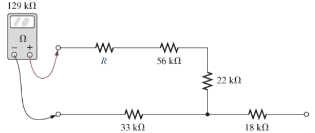
Find the resistance R, given the ohmmeter reading for each configuration of Fig. 5.95.
Expert Solution & Answer
Want to see the full answer?
Check out a sample textbook solution
Students have asked these similar questions
Given the power dissipated in each resistor in Fig. 5.8 as follows: P1= P5= 4.5W, P2 = 5W, P3= 1.332W,P4 = 2.668W . The total supply voltage is 12v, determine the resistances, R1 to R5.
Given the power dissipated in each resistor in Fig. 5.10, as follows:P1 =72W, P2 = 36W, P3= 18W, P4 = 12W, P5 = 6W, P6 = 0.5W, P7 = 0.333W, P8 = 0.05578 Wand P9 = 0.11156 W. Determine the value of resistances: R1 to R9.
For the series configuration in Fig. 5.92, constructed using standard value resistors:
a.) Without making a single calculation, which resistive element will have the most voltage across it? Which will have the least?
b.) Which resistor will have the most impact on the total resistance and the resulting current? Find the total resistance and the current.
Chapter 5 Solutions
Introductory Circuit Analysis (13th Edition)
Ch. 5 - For each configuration in Fig. 5.88, find the...Ch. 5 - For each configuration in Fig. 5.89, find the...Ch. 5 - Find the total resistance RT for each...Ch. 5 - Find the total resistance RT for each...Ch. 5 - For each circuit board in Fig. 5.92, �nd the...Ch. 5 - For the circuit in Fig. 5.93, composed of standard...Ch. 5 - For each configuration in Fig. 5.94, determine the...Ch. 5 - Find the resistance R, given the ohmmeter reading...Ch. 5 - What is the ohmmeter reading for each...Ch. 5 - For the series configuration in Fig. 5.97,...
Ch. 5 - For the series configuration in Fig. 5.98,...Ch. 5 - Find the applied voltage necessary to develop the...Ch. 5 - For each network in Fig. 5.100, constructed of...Ch. 5 - For each configuration in Fig. 5.101, what are the...Ch. 5 - For each configuration of Fig. 5.102, find the...Ch. 5 - For the circuit in Fig. 5.103, constructed of...Ch. 5 - Find the unknown quantities for the circuit of...Ch. 5 - Find the unknown quantities for the circuit in...Ch. 5 - Eight holiday lights are connected in series as...Ch. 5 - For the conditions specified in Fig. 5.107,...Ch. 5 - Combine the series voltage sources in Fig. 5.108,...Ch. 5 - Determine the current I and its direction for each...Ch. 5 - Find {he unknown voltage source and resistor for...Ch. 5 - Using Kirchhoffs voltage law, find the unknown...Ch. 5 - Find the current I for the network of Fig. 5.112....Ch. 5 - Using Kirchhoffs voltage law, determine the...Ch. 5 - Using Kirchhoffs voltage law, find the unknown...Ch. 5 - Determine the values of the unknown resistors in...Ch. 5 - For the configuration in Fig. 5.116, with standard...Ch. 5 - Using the voltage divider rule, find the indicated...Ch. 5 - Using the voltage divider rule or Kirchhoffs...Ch. 5 - Using the voltage divider rule or Kirchhoffs...Ch. 5 - Using the information provided, find the unknown...Ch. 5 - Using the voltage divider rule, �nd the unknown...Ch. 5 - Design a voltage divider circuit that will permit...Ch. 5 - Design the voltage divider in Fig. 5.122 such that...Ch. 5 - Find the voltage across each resistor in Fig....Ch. 5 - Design the circuit in Fig. 5.124 such that...Ch. 5 - Determine the voltages Va,Vb, and Vab for the...Ch. 5 - Determine the current I (with direction) and the...Ch. 5 - For the network in Fig. 5.127 determine the...Ch. 5 - Given the information appearing in Fig. 5.128,...Ch. 5 - Determine the values of R1,R2,R3, and R4 for the...Ch. 5 - For the network in Fig. 5.130, determine the...Ch. 5 - For the integrated circuit in Fig. 5.131,...Ch. 5 - For the integrated circuit in Fig. 5.132,...Ch. 5 - Find the internal resistance of a battery that has...Ch. 5 - Find the voltage to the load (full-and conditions)...Ch. 5 - Determine the current through the circuit in Fig....Ch. 5 - Use the computer to verify the results of Example...Ch. 5 - Use the computer to verify the results of Example...Ch. 5 - Use the computer to verify the results of Example...
Additional Engineering Textbook Solutions
Find more solutions based on key concepts
Identify the type of input and output configuration for each diff-amp in Figure 18-35.
Electronics Fundamentals: Circuits, Devices & Applications
The voltage source of the circuit shown in Fig. P1.29 is given by s(t)=25cos(4104t45)(V). Obtain an expression ...
Fundamentals of Applied Electromagnetics (7th Edition)
The current source in the circuit shown generates the current pulse
Find (a) v (0); (b) the instant of time gr...
Electric Circuits. (11th Edition)
Three point charges of equal magnitude q, that will yield a zero net electric field at the origin.
Engineering Electromagnetics
How many coulombs do 93.8 1016 electrons represent?
Principles Of Electric Circuits
Electric power systems provide energy in a variety of commercial and industrial settings. Make a list of system...
Principles and Applications of Electrical Engineering
Knowledge Booster


Learn more about
Need a deep-dive on the concept behind this application? Look no further. Learn more about this topic, electrical-engineering and related others by exploring similar questions and additional content below.Similar questions
- For the circuit in Fig. 5.88, composed of standard values: a. Which resistor will have the most impact on the total resistance? b. On an approximate basis, which resistors can be ignored when determining the total resistance? c. Find the total resistance, and comment on your results for parts (a) and (b).arrow_forwardFor each configuration in Fig. 5.85, find the individual (not combinations of) elements (voltages sources and/or resistors) that are in series. If necessary, use the fact that elements in series have the same current. Simply list those that satisfy the conditions for a series relationship.arrow_forwardFrom Fig. 5.4 which resistors consumes the least power?arrow_forward
- For each configuration in fig.5.94 determine the ohmmeter readingarrow_forwardFor the series configuration in Fig . 5.98 constructed using standard value resistor without making a single calculation, which resistive element will have the most voltage across it? Which will have the least? which resistor will have the most impact on the total resistance and the the resulting current ? Find the total resistance and the current. Find the voltage across each element and review your response to part (a)arrow_forward2. The ratio arms of the Kelvin bridge of Fig. 5-5 are 100 each. The galvanometer has an internal resistance of 500 and a current sensitivity of 200 mm/μA. The unknown resistance R, = 0.1002 2 and the standard resistance is set at 0.1000 n. A dc current of 10 A is passed through the standard and the unknown from a 2.2- V battery in series with a rheostat. The resistance of the yoke may be neglected. Calculate (a) the deflection of the galvanometer, and (b) the resistance unbalance required to produce a galvanometer deflection of 1 mm. E 2 H R2. in R3 www G Ry R₁ Rx wi Oarrow_forward
- 5.) When a resistance of 3 ohms is placed across the terminals of battery, the current is 2A. When the resistance is increased to 42 ohms, the current falls to 1 A. Find emf of battery and its internal resistance.arrow_forwardRefer to Fig. 5 – 3. Approximately, how much current flows through resistor R4?a. 3.6 mAdcb. 7.2 mAdcc. 0.9 mAdcd. 1.8 mAdcarrow_forwardDesign a charger circuit for mobile phone from:1.5 V AA BatterySelect the proper circuit topologies and components. (please explain in detail)arrow_forward
- 5.57 using fig 5.84 in the picturearrow_forwardContext: The results shown in table 5.0 were obtained using a potentiometer on a breadboard and measured with a DMM multimeter using the Ohmmeter function. Please answer the question below including as much detail and information as possible. Thank you very much.arrow_forwardP/ calculate the effective resisfance of the following combination of vesistance between pomts A and B then find veltage drop across each resistance when BD of 6ov is appliad between Puints A and B Aarrow_forward
arrow_back_ios
SEE MORE QUESTIONS
arrow_forward_ios
Recommended textbooks for you
 Introductory Circuit Analysis (13th Edition)Electrical EngineeringISBN:9780133923605Author:Robert L. BoylestadPublisher:PEARSON
 Delmar's Standard Textbook Of ElectricityElectrical EngineeringISBN:9781337900348Author:Stephen L. HermanPublisher:Cengage Learning
 Programmable Logic ControllersElectrical EngineeringISBN:9780073373843Author:Frank D. PetruzellaPublisher:McGraw-Hill Education
 Fundamentals of Electric CircuitsElectrical EngineeringISBN:9780078028229Author:Charles K Alexander, Matthew SadikuPublisher:McGraw-Hill Education
 Electric Circuits. (11th Edition)Electrical EngineeringISBN:9780134746968Author:James W. Nilsson, Susan RiedelPublisher:PEARSON
 Engineering ElectromagneticsElectrical EngineeringISBN:9780078028151Author:Hayt, William H. (william Hart), Jr, BUCK, John A.Publisher:Mcgraw-hill Education,
Introductory Circuit Analysis (13th Edition)
Electrical Engineering
ISBN:9780133923605
Author:Robert L. Boylestad
Publisher:PEARSON
Delmar's Standard Textbook Of Electricity
Electrical Engineering
ISBN:9781337900348
Author:Stephen L. Herman
Publisher:Cengage Learning
Programmable Logic Controllers
Electrical Engineering
ISBN:9780073373843
Author:Frank D. Petruzella
Publisher:McGraw-Hill Education
Fundamentals of Electric Circuits
Electrical Engineering
ISBN:9780078028229
Author:Charles K Alexander, Matthew Sadiku
Publisher:McGraw-Hill Education
Electric Circuits. (11th Edition)
Electrical Engineering
ISBN:9780134746968
Author:James W. Nilsson, Susan Riedel
Publisher:PEARSON
Engineering Electromagnetics
Electrical Engineering
ISBN:9780078028151
Author:Hayt, William H. (william Hart), Jr, BUCK, John A.
Publisher:Mcgraw-hill Education,
Current Divider Rule; Author: Neso Academy;https://www.youtube.com/watch?v=hRU1mKWUehY;License: Standard YouTube License, CC-BY