
Introductory Circuit Analysis (13th Edition)
13th Edition
ISBN: 9780133923605
Author: Robert L. Boylestad
Publisher: PEARSON
expand_more
expand_more
format_list_bulleted
Videos
Textbook Question
Chapter 20, Problem 7P
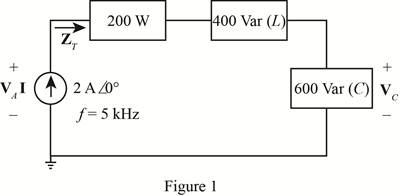
For the network of Fig. 20.54 :
a. Find the type and value of each element in each of the series loads.
b. Find the total impedance of the circuit.
c. Find the voltage across the current source.
d. Find the power factor of the series load.
e. Find the voltage across the capacitive load.
Expert Solution & Answer
Want to see the full answer?
Check out a sample textbook solution
Students have asked these similar questions
30. Which are used for power factor correction in industrial applications?
-
a. farads
b. capacitors
c. watts
d. coulombs
An alternating voltage of 110 volts is applied to a circuit with resistance of 8.66 Ohms,
inductance of 0.106 Henries, and capacitance of 75.8 microFarads. The frequency of
the voltage is 50 Hz. Determine:
a. The current in the circuit and its phase angle relative to the applied voltage.
b. The voltage drop across each component of the circuit.
c. The active and reactive power inputs to the circuit.
d. Draw (Not hand-sketch) the equivalent power triangle.
e. Is the RLC load of the circuit inductive or capacitive? Why?
Use 4 decimal places for your final answers.
Three identical loads with resistance of 75 ohms and inductive reactance of 57 ohms are connected in delta across a 1.28 kV, 3-phase, 60 Hz source.
a.) Find the line current.
b.) Find the power factor.
c.) What is the apparent power?
d.) If the values of resistance and reactance are interchanged, what is the reactive
power of the system?
Chapter 20 Solutions
Introductory Circuit Analysis (13th Edition)
Ch. 20 - For the battery of bulbs (purely resistive)...Ch. 20 - For the network of Fig. 20.49 : a. Find the...Ch. 20 - For the network of Fig. 20.50 : a. Determine the...Ch. 20 - For the system of Fig. 20.51 : a. Find the total...Ch. 20 - For the system of Fig. 20.52 : a. Find PT, QT. and...Ch. 20 - 6. For the system of Fig. 20.53 : a. Find PT, QT....Ch. 20 - For the network of Fig. 20.54 : a. Find the type...Ch. 20 - For the circuit of Fig. 20.55: a. Find the...Ch. 20 - For the network of Fig. 20.56 : a. Find Is. b....Ch. 20 - Repeat Problem 9 for the network of Fig. 20.57.
Ch. 20 - For the network of Fig. 20.58: a. Find the average...Ch. 20 - An electrical system is rated 10 kVA, 200 V at a...Ch. 20 - An electrical system is rated 5 kVA, 120 V, at a...Ch. 20 - For the system of Fig. 20.59: a. Find the total...Ch. 20 - Repeat Problem 14 for the system of Fig. 20.60.Ch. 20 - For the circuit of Fig. 20.61: Find the total...Ch. 20 - For the circuit of Fig. 20.62: Find the total...Ch. 20 - Prob. 18PCh. 20 - The load on a 120 V, 60 Hz supply is 5 kW...Ch. 20 - The loading of a factory on a 1000 V, 60 Hz system...Ch. 20 - a. A wattmeter is connected with its current coil...Ch. 20 - The voltage source in Fig. 20.64 delivers 660 VA...Ch. 20 - a. An air-core coil is connected to a 200 V, 60 Hz...Ch. 20 - a. The inductance of an air-core coil is 0.08 H....Ch. 20 - Using PSpice or Multisim, obtain a plot of...
Additional Engineering Textbook Solutions
Find more solutions based on key concepts
Assume a telephone signal travels through a cable at two-thirds the speed of light. How long does it take the s...
Electric Circuits (10th Edition)
The voltage source of the circuit shown in Fig. P1.29 is given by s(t)=25cos(4104t45)(V). Obtain an expression ...
Fundamentals of Applied Electromagnetics (7th Edition)
Identify the type of input and output configuration for each diff-amp in Figure 18-35.
Electronics Fundamentals: Circuits, Devices & Applications
Three point charges of equal magnitude q, that will yield a zero net electric field at the origin.
Engineering Electromagnetics
Explain the main function of each of the following major components of a PLC: a. Processor module (CPU) b. I/O ...
Programmable Logic Controllers
Find I0 and I1 in the circuit in Fig.P2.12.
Basic Engineering Circuit Analysis
Knowledge Booster


Learn more about
Need a deep-dive on the concept behind this application? Look no further. Learn more about this topic, electrical-engineering and related others by exploring similar questions and additional content below.Similar questions
- Variation of which of the following parameter is not consider as power quality problem for industry?VoltageCurrentPowerFrequencyarrow_forwardJ 0.5 A 350 W ; full-load, 0.8 p.f. .f. aximum. [96.56%arrow_forwardA factory has the following load with power factor of 0.9 lagging in each phase. Red phase 40 A, yellow phase 50 A and blue phase 60 A. If the supply is 400 V, three phase, four-wire, calculate:(a) the current in the neutral(b) the total active power.(c ) Draw a phasor diagram for phase and line quantities. Assume that, relative to the current in the red phase, the current in the yellow phase lags by 120° and that in the blue phase leads by 120°.5.arrow_forward
- Use 3 decimal places and box the final answer. A 4-ohm resistor is in series with a 7.96-mH inductor connected across a 110-V 60-Hz source. Determine : a) the impedance b) the input current c) the voltage across the resistor and the inductor d) Draw the phasor diagram showing the current and the voltages. e) The power factor and the power input to the circuit.arrow_forwardTransform the delta network in figure to wye network.arrow_forward1. Each phase of a delta-connected load comprises a resistor of 50 a and capacitor of 50 uF in series. Calculate (a) the line and phase currents (b) the total power and (c) the kilovoltamperes when the load is connected to a 440-V, 3-phase, 50-Hz supply. 2. Three similar-coils, A, B and C are available. Each coil has 9Q resistance and 12 Q reactance. They are connected in delta to a 3-phase, 440-V, 50-Hz supply. Calculate for this load: (a) the line cuIrent (c) the total kilovolt-amperes If the coils are reconnected in star, calculate for the new load the quantities named at (a), (b); (c) and (d) above. 3. Three similar choke coils are connected in star to a 3-phase supply. If the line currents are 15 A, the total power consumed is 11 kW and the volt-ampere input is 15 kVA, find the line and phase voltages, the VAR input and the reactance and resistance of each coil. [(a) 9.46 A; 5.46 A (b) 4480 W () 7.24 kVA] (b) the power factor (d) the total kilowatts [50.7 A; 0.6; 38.6 kVA; 23.16…arrow_forward
- In matlab, To obtain voltage and current waveforms from transmission line which tool can be used O a. voltage measurement O b. Three-phase VI measurment c. Series RLC branch O d. Parallel RLC loadarrow_forward1. Two impedances, Z1 =5230• ohms and Z2 = 10445• ohms, draw a current of 3.36 A when connected in series to a certain a.c. supply. Determine (a) the supply voltage, (b) the phase angle between the voltage and current, (c) the p.d. across Z1 and (d) the p.d. across Z2arrow_forwardThree coils are connected in delta across a 240 V, three-phase supply. The line current is 20 A. The total power delivered to the three coils is 6000 watts. Determine: the total load, in volt-amperes. the three-phase power factor. the current in each coil and the voltage across each coil. the impedance, in ohms, of each coilarrow_forward
- 12. The generation of "back voltage" is a significant factor for which of the following? O A. Capacitive reactance O B. Phase shift O C. Effective value D. Inductive reactancearrow_forwardComplete the sentence The power factor must be close to will be reduced To insure that losses in the transmission linesarrow_forwardFind magnitude of each branch, current, and the total current. What is the phase angle between the applied voltage and the total currentarrow_forward
arrow_back_ios
SEE MORE QUESTIONS
arrow_forward_ios
Recommended textbooks for you
 Introductory Circuit Analysis (13th Edition)Electrical EngineeringISBN:9780133923605Author:Robert L. BoylestadPublisher:PEARSON
 Delmar's Standard Textbook Of ElectricityElectrical EngineeringISBN:9781337900348Author:Stephen L. HermanPublisher:Cengage Learning
 Programmable Logic ControllersElectrical EngineeringISBN:9780073373843Author:Frank D. PetruzellaPublisher:McGraw-Hill Education
 Fundamentals of Electric CircuitsElectrical EngineeringISBN:9780078028229Author:Charles K Alexander, Matthew SadikuPublisher:McGraw-Hill Education
 Electric Circuits. (11th Edition)Electrical EngineeringISBN:9780134746968Author:James W. Nilsson, Susan RiedelPublisher:PEARSON
 Engineering ElectromagneticsElectrical EngineeringISBN:9780078028151Author:Hayt, William H. (william Hart), Jr, BUCK, John A.Publisher:Mcgraw-hill Education,
Introductory Circuit Analysis (13th Edition)
Electrical Engineering
ISBN:9780133923605
Author:Robert L. Boylestad
Publisher:PEARSON
Delmar's Standard Textbook Of Electricity
Electrical Engineering
ISBN:9781337900348
Author:Stephen L. Herman
Publisher:Cengage Learning
Programmable Logic Controllers
Electrical Engineering
ISBN:9780073373843
Author:Frank D. Petruzella
Publisher:McGraw-Hill Education
Fundamentals of Electric Circuits
Electrical Engineering
ISBN:9780078028229
Author:Charles K Alexander, Matthew Sadiku
Publisher:McGraw-Hill Education
Electric Circuits. (11th Edition)
Electrical Engineering
ISBN:9780134746968
Author:James W. Nilsson, Susan Riedel
Publisher:PEARSON
Engineering Electromagnetics
Electrical Engineering
ISBN:9780078028151
Author:Hayt, William H. (william Hart), Jr, BUCK, John A.
Publisher:Mcgraw-hill Education,
02 - Sinusoidal AC Voltage Sources in Circuits, Part 1; Author: Math and Science;https://www.youtube.com/watch?v=8zMiIHVMfaw;License: Standard Youtube License