
Introductory Circuit Analysis (13th Edition)
13th Edition
ISBN: 9780133923605
Author: Robert L. Boylestad
Publisher: PEARSON
expand_more
expand_more
format_list_bulleted
Videos
Textbook Question
Chapter 20, Problem 14P
For the system of Fig. 20.59:
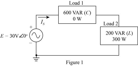
a. Find the total number of watts. volt-amperes reactive, volt-amperes, and Fp.
b. Find the current ls.
c. Draw the power triangle.
d. Find the type of elements and their impedance in ohms within each electrical box. (Assume that all elements of a load are in series.)
e. Verity that the result of part (b) is correct by finding the current ls using only the input voltage E and the results of part (d). Compare the value of ls with that obtained for part (b).
Expert Solution & Answer
Want to see the full answer?
Check out a sample textbook solution
Students have asked these similar questions
An alternating voltage of 110 volts is applied to a circuit with resistance of 8.66 Ohms,
inductance of 0.106 Henries, and capacitance of 75.8 microFarads. The frequency of
the voltage is 50 Hz. Determine:
a. The current in the circuit and its phase angle relative to the applied voltage.
b. The voltage drop across each component of the circuit.
c. The active and reactive power inputs to the circuit.
d. Draw (Not hand-sketch) the equivalent power triangle.
e. Is the RLC load of the circuit inductive or capacitive? Why?
1. A 6 ampere supply has a frequency of 25 Hz. Find the instantaneous value of current
a. at 0.00530 sec from zero going to the positive direction.
b. at 0.00530 sec from zero going to the negative direction.
c. at 530 degrees.
plase answer five a quesion option corrctly
9.In AC circuits, power consumed is
A.it depends on the supply voltage
B.product of voltage and current
C.it depends on the power factor (p.f.) of the circuit in addition to voltage and current
D.it depends on the magnitude of the circuit current
10A potential transformer is a
A.transformer used with an AC ammeter
B.transformer used with an AC voltmeter
C.transformer used with a DC voltmeter
D.transformer used with a DC ammeter
11. Define Per Unit Quantity
A/ Xp.u = x base / x actual per unit
B/ Xp.u = X actual / x base per unit
C/ Xp.u = x actual / x unit per unit
12./
VS= 1200<0º V
ZL= 50 + j60 ohm
ZS= j25ohm
By taking Zbase = 100 ohm, find Vs (p.u), Zs(p.u), ZL(p.u)
A.
Vs (p.u) = 1 < 00 p.u
Zs(p.u) = j0.20 p.u
ZL(p.u) = 66.42<390 p.u
B.
Vs (p.u) = 1 < 00 p.u
Zs(p.u) = j0.25 p.u
ZL(p.u) = 42.96<730 p.
C.
Vs (p.u) = 1 < 00 p.u
Zs(p.u) = j0.25 p.u
ZL(p.u) = 0.781<50.20 p.u
13. Which of…
Chapter 20 Solutions
Introductory Circuit Analysis (13th Edition)
Ch. 20 - For the battery of bulbs (purely resistive)...Ch. 20 - For the network of Fig. 20.49 : a. Find the...Ch. 20 - For the network of Fig. 20.50 : a. Determine the...Ch. 20 - For the system of Fig. 20.51 : a. Find the total...Ch. 20 - For the system of Fig. 20.52 : a. Find PT, QT. and...Ch. 20 - 6. For the system of Fig. 20.53 : a. Find PT, QT....Ch. 20 - For the network of Fig. 20.54 : a. Find the type...Ch. 20 - For the circuit of Fig. 20.55: a. Find the...Ch. 20 - For the network of Fig. 20.56 : a. Find Is. b....Ch. 20 - Repeat Problem 9 for the network of Fig. 20.57.
Ch. 20 - For the network of Fig. 20.58: a. Find the average...Ch. 20 - An electrical system is rated 10 kVA, 200 V at a...Ch. 20 - An electrical system is rated 5 kVA, 120 V, at a...Ch. 20 - For the system of Fig. 20.59: a. Find the total...Ch. 20 - Repeat Problem 14 for the system of Fig. 20.60.Ch. 20 - For the circuit of Fig. 20.61: Find the total...Ch. 20 - For the circuit of Fig. 20.62: Find the total...Ch. 20 - Prob. 18PCh. 20 - The load on a 120 V, 60 Hz supply is 5 kW...Ch. 20 - The loading of a factory on a 1000 V, 60 Hz system...Ch. 20 - a. A wattmeter is connected with its current coil...Ch. 20 - The voltage source in Fig. 20.64 delivers 660 VA...Ch. 20 - a. An air-core coil is connected to a 200 V, 60 Hz...Ch. 20 - a. The inductance of an air-core coil is 0.08 H....Ch. 20 - Using PSpice or Multisim, obtain a plot of...
Knowledge Booster


Learn more about
Need a deep-dive on the concept behind this application? Look no further. Learn more about this topic, electrical-engineering and related others by exploring similar questions and additional content below.Similar questions
- Electrical Engineering Questionarrow_forwardQ1) A power is to be distributed to the consumers either by a 3-wire DC system or by a 3- phase three wire system .Compare the amount of copper required in the two systems .Assume the same voltage between the outer wire and neutral wire . same percentage loss, balanced load and unity power factor . the middle wires are of half of cross-sectional area as that of outersarrow_forward13. A rotary standard with a K of % whr per revolution and a multiplier of 3 makes 42.4 revolutions during the testing of a watthour meter with a K,, of 1.8 whr per revolution. If the meter has two current coils connected in series and makes 48 revolutions, what is the percent registration of the meter under test? A. 79.5% B. 98.1% C. 119 % D. 102%arrow_forward
- 2. The SONEL thermal plant in Limbe supplies SONARA with 1.0 MV at a p.d of 1.0 x 10⁴v The total resistance between the power station and the factory is 0.52. a. What is the power output of the thermal plant b. Explain why the power station output voltage is always stepped up before transmission over a long distancearrow_forwardVariation of which of the following parameter is not consider as power quality problem for industry?VoltageCurrentPowerFrequencyarrow_forwardFind total number of watts, volt ampere reactive power.arrow_forward
- in a work environment 50 Hz 220V Find the following hardware in the power system 1.. .piece 100W incandescent filament lamp 2.power.. .kW efficient %88 power factor 0.85 asynchronous motor with 3.power 2000W a heater with power factor of the power system. .Calculate the capacity of the capacitor that needs to be added to the circuit in order to determine the places to be written in the blankarrow_forwardDetermine the average value of the current through the load resistor.arrow_forwardAn impedance coil takes 10A and absorbs 250 W when connected across a 220V, 60Hz source. What power will it absorb when connected across 110 V, 25 Hz mains? a. 539 W b. 239 W c. 439 W d. 339 Warrow_forward
- Identify the low voltage system from the following. a. primary distribution O b. Secondary distribution c. Generation O d. secondary transmissionarrow_forwardAnswer the following problems in a short/long bond paper size. Round off your answer up to 2 decimals, if applicable. Show your complete solution and box your final answer. You may not copy the problem. 1. Two properly connected wattmeters are used to measure the power drawn by a 440 V squirrel-cage induction motor. If the wattmeters read 60 kW and 32 kW, find the line current drawn by the motor. 2. A 3-phase feeder carries two lagging balanced loads. The power drawn in each is measured by a standard two wattmeter method, giving the following readings: First load: W; = 160 kW; W2 = 96 KW and second load: W. = 90 kW; W; = 48 KW. Find the total kVA load on the feeder. 3. Two-wattmeter method is used to test a 25 hp, 230 V, 1800 rpm, 60 Hz, 3-phase induction motor. If the readings of the wattmeters are 13,400 Ww and 7,400 W, find the power factor of the load. 4. The input power to a 3-phase induction motor running without a load is measured by a two wattmeter method. One wattmeter reads…arrow_forward1.3 A 240 volts 50 Hz single phase ac source supplies a series load consisting of a resistor (40 ohms), a reactor (127.324 mH) and a capacitor (318.3 µF). Suppose that the frequency of the source can be varied at will. 1.3.1 Determine the maximum load current. 1.3.2 Determine the source frequency for maximum load current. 1.3.3 What is the name of this frequency? 1.3.4 Determine the load power factor. 1.3.5 What is the name of the sourcearrow_forward
arrow_back_ios
SEE MORE QUESTIONS
arrow_forward_ios
Recommended textbooks for you
 Introductory Circuit Analysis (13th Edition)Electrical EngineeringISBN:9780133923605Author:Robert L. BoylestadPublisher:PEARSON
 Delmar's Standard Textbook Of ElectricityElectrical EngineeringISBN:9781337900348Author:Stephen L. HermanPublisher:Cengage Learning
 Programmable Logic ControllersElectrical EngineeringISBN:9780073373843Author:Frank D. PetruzellaPublisher:McGraw-Hill Education
 Fundamentals of Electric CircuitsElectrical EngineeringISBN:9780078028229Author:Charles K Alexander, Matthew SadikuPublisher:McGraw-Hill Education
 Electric Circuits. (11th Edition)Electrical EngineeringISBN:9780134746968Author:James W. Nilsson, Susan RiedelPublisher:PEARSON
 Engineering ElectromagneticsElectrical EngineeringISBN:9780078028151Author:Hayt, William H. (william Hart), Jr, BUCK, John A.Publisher:Mcgraw-hill Education,
Introductory Circuit Analysis (13th Edition)
Electrical Engineering
ISBN:9780133923605
Author:Robert L. Boylestad
Publisher:PEARSON
Delmar's Standard Textbook Of Electricity
Electrical Engineering
ISBN:9781337900348
Author:Stephen L. Herman
Publisher:Cengage Learning
Programmable Logic Controllers
Electrical Engineering
ISBN:9780073373843
Author:Frank D. Petruzella
Publisher:McGraw-Hill Education
Fundamentals of Electric Circuits
Electrical Engineering
ISBN:9780078028229
Author:Charles K Alexander, Matthew Sadiku
Publisher:McGraw-Hill Education
Electric Circuits. (11th Edition)
Electrical Engineering
ISBN:9780134746968
Author:James W. Nilsson, Susan Riedel
Publisher:PEARSON
Engineering Electromagnetics
Electrical Engineering
ISBN:9780078028151
Author:Hayt, William H. (william Hart), Jr, BUCK, John A.
Publisher:Mcgraw-hill Education,
Inductors Explained - The basics how inductors work working principle; Author: The Engineering Mindset;https://www.youtube.com/watch?v=KSylo01n5FY;License: Standard Youtube License