
Introductory Circuit Analysis (13th Edition)
13th Edition
ISBN: 9780133923605
Author: Robert L. Boylestad
Publisher: PEARSON
expand_more
expand_more
format_list_bulleted
Videos
Textbook Question
Chapter 20, Problem 16P
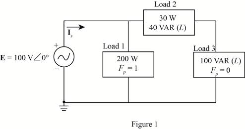
For the circuit of Fig. 20.61:
- Find the total number of watts, volt-amperes reactive, volt-amperes, and Fp.
- Find the current Is.
- Find the type of elements and their impedance in each box. (Assume that the elements within each box are in series.)
Expert Solution & Answer
Want to see the full answer?
Check out a sample textbook solution
Students have asked these similar questions
For the network of Fig. 20.56:
a. Find Is.
b. Find the average power delivered to each element.
c. Find the reactive power for each element.
d. Find the apparent power for each element.
e. Find PT, QT, ST, and Fp for the system.
f. Sketch the power triangle.
Please answer all subpart either 100% dislike is ready please all subpart in short and clear handwriting or typing
Variation of which of the following parameter is not consider as power quality problem for industry?VoltageCurrentPowerFrequency
if Pd exceeds Pg generation, what will be the effects on the frequency of the power systems
Chapter 20 Solutions
Introductory Circuit Analysis (13th Edition)
Ch. 20 - For the battery of bulbs (purely resistive)...Ch. 20 - For the network of Fig. 20.49 : a. Find the...Ch. 20 - For the network of Fig. 20.50 : a. Determine the...Ch. 20 - For the system of Fig. 20.51 : a. Find the total...Ch. 20 - For the system of Fig. 20.52 : a. Find PT, QT. and...Ch. 20 - 6. For the system of Fig. 20.53 : a. Find PT, QT....Ch. 20 - For the network of Fig. 20.54 : a. Find the type...Ch. 20 - For the circuit of Fig. 20.55: a. Find the...Ch. 20 - For the network of Fig. 20.56 : a. Find Is. b....Ch. 20 - Repeat Problem 9 for the network of Fig. 20.57.
Ch. 20 - For the network of Fig. 20.58: a. Find the average...Ch. 20 - An electrical system is rated 10 kVA, 200 V at a...Ch. 20 - An electrical system is rated 5 kVA, 120 V, at a...Ch. 20 - For the system of Fig. 20.59: a. Find the total...Ch. 20 - Repeat Problem 14 for the system of Fig. 20.60.Ch. 20 - For the circuit of Fig. 20.61: Find the total...Ch. 20 - For the circuit of Fig. 20.62: Find the total...Ch. 20 - Prob. 18PCh. 20 - The load on a 120 V, 60 Hz supply is 5 kW...Ch. 20 - The loading of a factory on a 1000 V, 60 Hz system...Ch. 20 - a. A wattmeter is connected with its current coil...Ch. 20 - The voltage source in Fig. 20.64 delivers 660 VA...Ch. 20 - a. An air-core coil is connected to a 200 V, 60 Hz...Ch. 20 - a. The inductance of an air-core coil is 0.08 H....Ch. 20 - Using PSpice or Multisim, obtain a plot of...
Additional Engineering Textbook Solutions
Find more solutions based on key concepts
Identify the type of input and output configuration for each diff-amp in Figure 18-35.
Electronics Fundamentals: Circuits, Devices & Applications
What is the color code for a 365- five-band precision resistor with a tolerance of 5 percent?
ELECTRICITY FOR TRADES (LOOSELEAF)
How many coulombs do 93.8 1016 electrons represent?
Principles Of Electric Circuits
Find I0 and I1 in the circuit in Fig.P2.12.
Basic Engineering Circuit Analysis
Does the severity of an electric shock increase ordecrease with eh of the following changes? a. A decrease in t...
Electric Motors and Control Systems
Explain the main function of each of the following major components of a PLC: a. Processor module (CPU) b. I/O ...
Programmable Logic Controllers
Knowledge Booster


Learn more about
Need a deep-dive on the concept behind this application? Look no further. Learn more about this topic, electrical-engineering and related others by exploring similar questions and additional content below.Similar questions
- An alternating voltage of 110 volts is applied to a circuit with resistance of 8.66 Ohms, inductance of 0.106 Henries, and capacitance of 75.8 microFarads. The frequency of the voltage is 50 Hz. Determine: a. The current in the circuit and its phase angle relative to the applied voltage. b. The voltage drop across each component of the circuit. c. The active and reactive power inputs to the circuit. d. Draw (Not hand-sketch) the equivalent power triangle. e. Is the RLC load of the circuit inductive or capacitive? Why?arrow_forwardWhat is the maximum power that can be transferred to the marked variable (in watts)? Ans. cannot be in terms of V, or Iş 12N Is -> Vs RL ЗА SW1arrow_forward69 js 28 Problom in E, fov For the circuit shown in figure, tind: D Totel current CIt) هندسة حاسبات مرحلة أولى مسائي 31/01/22arrow_forward
- After studding the network answer the questions. 1. Find Is. 2. Find the current passing through the capacitor 3. Find the average power delivered to each element. 4. Find the reactive power for each element. 5. Find the apparent power for each element. 6. Find the total number of watts, volt-amperes reactive, and volt-amperes of the circuit. 7. Find the power factor for the system. 8. Sketch the power triangle. R E = 50 V Z60° 10 Ω 4 0 f = 60 Hzarrow_forward2-0-ea:: anc20Mass:c20Transter-conuştüru ci.pdf Dersler Z Zimbra Gelen Kutu.. C eemanonline.com.t. e Cağrı Merkezi 66% PREUMINARY INFORMATION: Electrical compensation is a major scale subject that every business/facility is Included. The power factor should be compensated to change the reactive power up to some specific values since some reactive power limits are not good for consumption and generation of the electricity (this is a far large topic which also forms some subbranches, for more information and specification please research yourself). For this reason, it is an obligation to use a compensator system for both manufacturers (wind farms/hydroelectric power plants/etc.) and consumers (residents/factories/etc.). These issues are regulated by official directives. EXERCISE STEPS: A single-phase load has an active power of P = 2 kW at 180 V @60HZ and the power factor is coso = 0.75. This motor is compensated to coso = 0.85 using a parallel capacitor (the load is modelled as series…arrow_forwardUse the image to answer the 3 part question. A)determine the impedance of the circuit. B)determine the average power provided by the source to the circuit. C) Determine Vr the maximum voltage drop through the resistor and Vc max the maximum voltage drop through the capacitorarrow_forward
- ?? The step down chopper is operating at 1 kHz. Other data are V = 240 V, L = 10 mH, R = 10 and duty cycle 60%. (a) current. Determine the DC component of the load current and the peak-to-peak ripple in the load (b) By how much will the above values change if the frequency is increased to 2 kHz other data remaining the same. (c) What will the change in the values determined in (a) if the frequency is unchanged but the inductance value is increased to 20 mH, other data remaining the same.arrow_forward7. Two coils are connected in series. With 2 A d.c. through the circuit, the p.ds. across the coils are 20 and 30 V respectively. With 2 A a.c. at 40 Hz, the p.ds. across the coils are 140 and 100 V respectively. If the two colls in series are connected to a 230-V, 50-Hz supply, całculate (a) the current (b) the power (c) the power factor,arrow_forwardComplete the sentence The power factor must be close to will be reduced To insure that losses in the transmission linesarrow_forward
- 8. Find the average value of each voltage in Fig. 5. inn. m. 5V 100 V ov- ov- (a) (b) 20 V OV 10 V -15 V ov+ (c) (d) Fig. 5 9. Consider the circuit in Fig. a. What type of circuit is this? b. What is the total peak secondary voltage? c. Find the peak voltage across each half of the secondary. d. Sketch the voltage waveform across Rµ. e. What is the PIV for each diode? 4:1 110 V rms RL 1.0 kfl D2 Fig. 6arrow_forwardWhat is reactive power compensation? 22- Kompanzasyon nedir? Frequency regulation A) Frekansın ayarlanması Power regulation B) Gücün ayarlanması Power factor correction C) Güç katsayısının düzeltilmesi Voltage regulation O D) Gerilimin ay amasiarrow_forward1) Determine the total current supplied by the source and the current in each branch. 2) Sketch a fully labelled phasor diagram showing all voltage and currents in the circuit. 3) Determine the active power delivered by the source voltage. 4) Determine the reactive power. 5) Sketch the power triangle. 6) Comment on the significance of the power factor and briefly state how it can be improved.arrow_forward
arrow_back_ios
SEE MORE QUESTIONS
arrow_forward_ios
Recommended textbooks for you
 Introductory Circuit Analysis (13th Edition)Electrical EngineeringISBN:9780133923605Author:Robert L. BoylestadPublisher:PEARSON
 Delmar's Standard Textbook Of ElectricityElectrical EngineeringISBN:9781337900348Author:Stephen L. HermanPublisher:Cengage Learning
 Programmable Logic ControllersElectrical EngineeringISBN:9780073373843Author:Frank D. PetruzellaPublisher:McGraw-Hill Education
 Fundamentals of Electric CircuitsElectrical EngineeringISBN:9780078028229Author:Charles K Alexander, Matthew SadikuPublisher:McGraw-Hill Education
 Electric Circuits. (11th Edition)Electrical EngineeringISBN:9780134746968Author:James W. Nilsson, Susan RiedelPublisher:PEARSON
 Engineering ElectromagneticsElectrical EngineeringISBN:9780078028151Author:Hayt, William H. (william Hart), Jr, BUCK, John A.Publisher:Mcgraw-hill Education,
Introductory Circuit Analysis (13th Edition)
Electrical Engineering
ISBN:9780133923605
Author:Robert L. Boylestad
Publisher:PEARSON
Delmar's Standard Textbook Of Electricity
Electrical Engineering
ISBN:9781337900348
Author:Stephen L. Herman
Publisher:Cengage Learning
Programmable Logic Controllers
Electrical Engineering
ISBN:9780073373843
Author:Frank D. Petruzella
Publisher:McGraw-Hill Education
Fundamentals of Electric Circuits
Electrical Engineering
ISBN:9780078028229
Author:Charles K Alexander, Matthew Sadiku
Publisher:McGraw-Hill Education
Electric Circuits. (11th Edition)
Electrical Engineering
ISBN:9780134746968
Author:James W. Nilsson, Susan Riedel
Publisher:PEARSON
Engineering Electromagnetics
Electrical Engineering
ISBN:9780078028151
Author:Hayt, William H. (william Hart), Jr, BUCK, John A.
Publisher:Mcgraw-hill Education,
Inductors Explained - The basics how inductors work working principle; Author: The Engineering Mindset;https://www.youtube.com/watch?v=KSylo01n5FY;License: Standard Youtube License