
Concept explainers
Videos
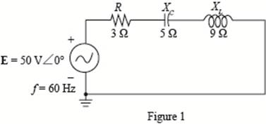
For the network of Fig. 20.49 :
a. Find the average power delivered to each element.
b. Find the reactive power for each element.
c. Find the apparent power for each element.
d. Find the total number of watts, volt-amperes reactive, and volt-amperes, and the power factor FP of the circuit.
e. Sketch the power triangle.
f. Find the energy dissipated by the resistor over one full cycle of the input voltage.
g. Find the energy stored or returned by the capacitor and the inductor over one half-cycle of the power curve for each.
Want to see the full answer?
Check out a sample textbook solution
Chapter 20 Solutions
Introductory Circuit Analysis (13th Edition)
Additional Engineering Textbook Solutions
Electric Motors and Control Systems
Principles Of Electric Circuits
Electronics Fundamentals: Circuits, Devices & Applications
Fundamentals of Electric Circuits
Fundamentals of Applied Electromagnetics (7th Edition)
Basic Engineering Circuit Analysis


- A 5-ohm resistor is connected in series with a 25 micro-farad capacitor. A source voltage of 158 volts, 50 Hz supplies the combination. Determine the following: a. Circulating current b. Voltage across the resistor c. Voltage across the capacitor d. Real power supplied by the source e. Reactive power supplied by the source f. Apparent power of the circuit g. Power factor of the entire circuitarrow_forwardAn alternating voltage of 110 volts is applied to a circuit with resistance of 8.66 Ohms, inductance of 0.106 Henries, and capacitance of 75.8 microFarads. The frequency of the voltage is 50 Hz. Determine: a. The current in the circuit and its phase angle relative to the applied voltage. b. The voltage drop across each component of the circuit. c. The active and reactive power inputs to the circuit. d. Draw (Not hand-sketch) the equivalent power triangle. e. Is the RLC load of the circuit inductive or capacitive? Why?arrow_forwardi. Three identical coils connected in star, take a total power of 1.5 kW at a pf of 0.2 lagging from a 3-phase 400-V, 60 Hz line. Find the inductance of each coil.arrow_forward
- Q20. A 230 V, 50 Hz AC supply is applied to a coil of 0.16 H inductance and 6.5 Q resistance connected in series with a capacitor. The power consumed by the circuit is 2.61 KW at 0.566 pf lagging. Estimate the following: i. Current flowing through the circuit. i. Phase angle between current and voltage. iii. The value of the capacitor.arrow_forwardUse the image to answer the 3 part question. A)determine the impedance of the circuit. B)determine the average power provided by the source to the circuit. C) Determine Vr the maximum voltage drop through the resistor and Vc max the maximum voltage drop through the capacitorarrow_forward120 VRMS 1 Select one: OA. 360 VRMS OB. 40 VRMS OC. 80 VRMS OD. 240 VRMS لشما What is the secondary voltage if the turns ratio is 1:3?arrow_forward
- 1. An electro-magnet draws 3 kW of active power and 4 kvar of reactive power. a. Calculate the apparent power. b. Calculate the power factor. 2. A capacitor drawing 4 kvar is placed in parallel with the electro-magnet of Question 1. a. Calculate the new value of apparent power b. What is the new value of reactive power? c. What is the value of active power? d. What is the new power factor?arrow_forwardA single phase motor draws a current of 5 A from the 60 Hz line. The Power Factor of the motor is 0.65. i. Calculate the active power absorbed by the motor. ii. Calculate the reactive power supplied by the line.arrow_forwardThree impedances 10-j30 are connected in star across 100 volts 60 HZ Line to Neutral, Calculate a. PF of the load b. Line Current c. Active Power d. Apparent Powerarrow_forward
- 1.58 A single-phase ac voltage source has 200 V rms and a system connected consumes an active power of 300 W. What is the reactive power consumed by the system if 2.5 A rms current is drawn?arrow_forwardProblem 4 An electric saw, a wood shaper, and a motor load of a workshop establish a 18 kVA power demand at 0.5 power factor lagging on a 208 V, 60 Hz supply. a) Establish the power triangle for the load. b) Determine the power-factor capacitor that must be place in parallel with the load to raise the power factor to 0.9 lagging. c) Determine the change in supply current from the uncompensated to the compensated system. d) Determine the power-factor capacitor that must be placed in parallel with the load to raise the power factor to unity.arrow_forwardWhat is the common frequency of alternating current in the United States? Select one: A. 25 HERTZ B. 50 HERTZ C. 60 HERTZ D. NONE OF THE ABOVEarrow_forward
 Introductory Circuit Analysis (13th Edition)Electrical EngineeringISBN:9780133923605Author:Robert L. BoylestadPublisher:PEARSON
 Delmar's Standard Textbook Of ElectricityElectrical EngineeringISBN:9781337900348Author:Stephen L. HermanPublisher:Cengage Learning
 Programmable Logic ControllersElectrical EngineeringISBN:9780073373843Author:Frank D. PetruzellaPublisher:McGraw-Hill Education
 Fundamentals of Electric CircuitsElectrical EngineeringISBN:9780078028229Author:Charles K Alexander, Matthew SadikuPublisher:McGraw-Hill Education
 Electric Circuits. (11th Edition)Electrical EngineeringISBN:9780134746968Author:James W. Nilsson, Susan RiedelPublisher:PEARSON
 Engineering ElectromagneticsElectrical EngineeringISBN:9780078028151Author:Hayt, William H. (william Hart), Jr, BUCK, John A.Publisher:Mcgraw-hill Education,