
Introductory Circuit Analysis (13th Edition)
13th Edition
ISBN: 9780133923605
Author: Robert L. Boylestad
Publisher: PEARSON
expand_more
expand_more
format_list_bulleted
Videos
Textbook Question
Chapter 20, Problem 3P
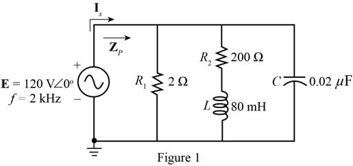
For the network of Fig. 20.50 :
a. Determine the total real, reactive, and apparent power for each parallel branch.
b. Draw the power triangle.
c. Find the total impedance and power factor of the network.
d. Find the source current ls.
Expert Solution & Answer
Want to see the full answer?
Check out a sample textbook solution
Students have asked these similar questions
a. The equivalent impedance of the connection
b. The phasor and instantaneous current flowing through the connection
c. Draw the phasor diagram of the supply voltage and the total current. What is the phase difference of the two?
For the given circuit below
a. Calculate E, IR, and IL, in phasor form.b. Calculate the total power factor (leading or lagging) and the average power delivered to the circuit.c. Draw the admittance diagram and draw the phasor diagram of the currents Is, IR, and IL, and the voltage E.
A 5-ohm resistor is connected in series with a 25 micro-farad capacitor. A source voltage of
158 volts, 50 Hz supplies the combination. Determine the following:
a. Circulating current
b. Voltage across the resistor
c. Voltage across the capacitor
d. Real power supplied by the source
e. Reactive power supplied by the source
f. Apparent power of the circuit
g. Power factor of the entire circuit
Chapter 20 Solutions
Introductory Circuit Analysis (13th Edition)
Ch. 20 - For the battery of bulbs (purely resistive)...Ch. 20 - For the network of Fig. 20.49 : a. Find the...Ch. 20 - For the network of Fig. 20.50 : a. Determine the...Ch. 20 - For the system of Fig. 20.51 : a. Find the total...Ch. 20 - For the system of Fig. 20.52 : a. Find PT, QT. and...Ch. 20 - 6. For the system of Fig. 20.53 : a. Find PT, QT....Ch. 20 - For the network of Fig. 20.54 : a. Find the type...Ch. 20 - For the circuit of Fig. 20.55: a. Find the...Ch. 20 - For the network of Fig. 20.56 : a. Find Is. b....Ch. 20 - Repeat Problem 9 for the network of Fig. 20.57.
Ch. 20 - For the network of Fig. 20.58: a. Find the average...Ch. 20 - An electrical system is rated 10 kVA, 200 V at a...Ch. 20 - An electrical system is rated 5 kVA, 120 V, at a...Ch. 20 - For the system of Fig. 20.59: a. Find the total...Ch. 20 - Repeat Problem 14 for the system of Fig. 20.60.Ch. 20 - For the circuit of Fig. 20.61: Find the total...Ch. 20 - For the circuit of Fig. 20.62: Find the total...Ch. 20 - Prob. 18PCh. 20 - The load on a 120 V, 60 Hz supply is 5 kW...Ch. 20 - The loading of a factory on a 1000 V, 60 Hz system...Ch. 20 - a. A wattmeter is connected with its current coil...Ch. 20 - The voltage source in Fig. 20.64 delivers 660 VA...Ch. 20 - a. An air-core coil is connected to a 200 V, 60 Hz...Ch. 20 - a. The inductance of an air-core coil is 0.08 H....Ch. 20 - Using PSpice or Multisim, obtain a plot of...
Additional Engineering Textbook Solutions
Find more solutions based on key concepts
Design an ideal inverting op-amp circuit such that the voltage gain is Av=25 . The maximum current in any resis...
Microelectronics: Circuit Analysis and Design
Three point charges of equal magnitude q, that will yield a zero net electric field at the origin.
Engineering Electromagnetics
With respect to the circuit in Fig. 5.90, (a) employ Thévenin’s theorem to determine the equivalent network see...
Loose Leaf for Engineering Circuit Analysis Format: Loose-leaf
The voltage source of the circuit shown in Fig. P1.29 is given by s(t)=25cos(4104t45)(V). Obtain an expression ...
Fundamentals of Applied Electromagnetics (7th Edition)
Explain the main function of each of the following major components of a PLC: a. Processor module (CPU) b. I/O ...
Programmable Logic Controllers
Electric power systems provide energy in a variety of commercial and industrial settings. Make a list of system...
Principles and Applications of Electrical Engineering
Knowledge Booster


Learn more about
Need a deep-dive on the concept behind this application? Look no further. Learn more about this topic, electrical-engineering and related others by exploring similar questions and additional content below.Similar questions
- For a system with total complex power of 10000 + 7500j VA, nominal voltage of 250 angle 30 deg. and 50HZ system frequency. Vrms. When this system power factor is raised to power factor 0.9 leading. Determine the new current. 44.44 angle 55.84 deg. A 44.44 angle -55.84 deg. A 50 angle -66.87 deg. A 50 angle 66.87 deg. Aarrow_forward1. A motor load consists of a resistance of 6 Ohms in series with an inductance of 12 mH. Assume 120Vac, 60 Hz supply. a. What is the complex impedance of the load? b. What is the ac current through this load? c. What is theta, the angle between voltage and current through this load? d. What is the power factor? e. What capacitance should be added in parallel with this load to correct the power factor to 1? f. What is the current from the supply when the power factor is corrected?arrow_forwardlši vl pir:10 Expert Q&A + 1. For the circuit in Figure: a. Determine I, VR, and Ve in phasor form. b. Calculate the total power factor, and indicate whether it is leading or lagging. c. Calculate the average power delivered to the circuit. d. Draw the impedance diagram. e. Find the voltages VR and Vcusing the voltage divider rule and compare them with the results of part(a) above. + Uc - + Ug - 30 2 L = 0.2 H L =0.2 H C = 4 µF e = V2(20) sin(377t + 40°) Expert Answer Home Search More IIarrow_forward
- Question 1: Based on figure below: a. Find the total impedance Z, in polar form b. Draw the impedance diagram c. Find the current I and voltages VR, V, and Vc in phasor form d. Draw the phasor diagram of the voltages E, VR, Viand Vc, and the current I. e. Verify Kirchhoff's voltage law around the closed loop. f. Find the average power delivered to the circuit g. Find the power factor of the circuit, and indicate whether it is leading or lagging. h. What happened if Xc= 20 ? Please explain. R- 40 X, = 6N Xc = 10 N %3D + UR + UL + vc e = 70.7 sin 377t|arrow_forward1- Determine YT and ZT 2- Sketch the admittance diagram. 3- Find E and IL. 4- Compute the power factor of the network and the power delivered to the network 5- Determine the equivalent series circuit as far as the terminal charac-teristics of the network are concerned. 6- Using the equivalent circuit developed in part e, calculate E, and compare it with the result of part c. 7- Determine the power delivered to the network, and compare it with the solution of part (d). 8- Determine the equivalent parallel network from the equivalent series circuit, and calculate the total admittance Yr. Compare the result with the solution of part (a). i= √2 (12) sin 1000r ZT R₁100 R₂40 L₁6 mH L12 mH 80 μF 20 µFarrow_forwardAn alternating voltage of 110 volts is applied to a circuit with resistance of 8.66 Ohms, inductance of 0.106 Henries, and capacitance of 75.8 microFarads. The frequency of the voltage is 50 Hz. Determine: a. The current in the circuit and its phase angle relative to the applied voltage. b. The voltage drop across each component of the circuit. c. The active and reactive power inputs to the circuit. d. Draw (Not hand-sketch) the equivalent power triangle. e. Is the RLC load of the circuit inductive or capacitive? Why?arrow_forward
- A 5-ohm resistor is connected in series with a 25 micro-farad capacitor. A source voltage of158 volts, 50 Hz supplies the combination. Determine the following: e. Reactive power supplied by the sourcef. Apparent power of the circuitg. Power factor of the entire circuitarrow_forwardUse the image to answer the 3 part question. A)determine the impedance of the circuit. B)determine the average power provided by the source to the circuit. C) Determine Vr the maximum voltage drop through the resistor and Vc max the maximum voltage drop through the capacitorarrow_forward2. Given that vs(t) = 100cos cot volts, f= 50 Hz, R₁ = 100 ohm, R₂ = 200 ohm, RL = 250 ohm, C = 40 uF, L = 0.5 H. R1 L Vs =C VL R₁ Problem 2 a.) Find the power in the load RL-L b.) Find R and L so that the average power of the RI-L two-pole will be maximum. R2 Zxarrow_forward
- A 400 V of 50 Hz is supplying a three-phase load of 150kW that is located 150 m away from the distribution board. It is operated with two other power circuits in the ground of soil resistivity of 1.2 °C.m/W at a depth of 0.8 m in a temperature of 30 °C. Find the size of Cu power cable which is required for this load by attaching relevant tables from Internet. DB 150m 150 kW LOADarrow_forwardXL=62 R1=40 Is R2=90 + + E1=100V20° AC R3=80 V3 Xc=72 ZT a. Calculate the total impedance (ZT). b. Compute the source current (Is). c. Find the current across the capacitor Xc. d. Calculate the voltage across the resistor R3. e. Find the average power delivered to the circuit (PT). f. Find the total power factor (Fp).arrow_forwardThree Impedances each of (8 - j24)2 are connected in mesh across a three-phase 420V ac supply. Determine the phase current, line current, active power, reactive power drawn from supply. Also draw the Phasor diagram for the mesh connection and marks the Line current ,phase current line voltage and phase angle between phase current and pahse voltage. phase current (Ip) Line current real power reactive powerarrow_forward
arrow_back_ios
SEE MORE QUESTIONS
arrow_forward_ios
Recommended textbooks for you
 Introductory Circuit Analysis (13th Edition)Electrical EngineeringISBN:9780133923605Author:Robert L. BoylestadPublisher:PEARSON
 Delmar's Standard Textbook Of ElectricityElectrical EngineeringISBN:9781337900348Author:Stephen L. HermanPublisher:Cengage Learning
 Programmable Logic ControllersElectrical EngineeringISBN:9780073373843Author:Frank D. PetruzellaPublisher:McGraw-Hill Education
 Fundamentals of Electric CircuitsElectrical EngineeringISBN:9780078028229Author:Charles K Alexander, Matthew SadikuPublisher:McGraw-Hill Education
 Electric Circuits. (11th Edition)Electrical EngineeringISBN:9780134746968Author:James W. Nilsson, Susan RiedelPublisher:PEARSON
 Engineering ElectromagneticsElectrical EngineeringISBN:9780078028151Author:Hayt, William H. (william Hart), Jr, BUCK, John A.Publisher:Mcgraw-hill Education,
Introductory Circuit Analysis (13th Edition)
Electrical Engineering
ISBN:9780133923605
Author:Robert L. Boylestad
Publisher:PEARSON
Delmar's Standard Textbook Of Electricity
Electrical Engineering
ISBN:9781337900348
Author:Stephen L. Herman
Publisher:Cengage Learning
Programmable Logic Controllers
Electrical Engineering
ISBN:9780073373843
Author:Frank D. Petruzella
Publisher:McGraw-Hill Education
Fundamentals of Electric Circuits
Electrical Engineering
ISBN:9780078028229
Author:Charles K Alexander, Matthew Sadiku
Publisher:McGraw-Hill Education
Electric Circuits. (11th Edition)
Electrical Engineering
ISBN:9780134746968
Author:James W. Nilsson, Susan Riedel
Publisher:PEARSON
Engineering Electromagnetics
Electrical Engineering
ISBN:9780078028151
Author:Hayt, William H. (william Hart), Jr, BUCK, John A.
Publisher:Mcgraw-hill Education,
Inductors Explained - The basics how inductors work working principle; Author: The Engineering Mindset;https://www.youtube.com/watch?v=KSylo01n5FY;License: Standard Youtube License