
Introductory Circuit Analysis (13th Edition)
13th Edition
ISBN: 9780133923605
Author: Robert L. Boylestad
Publisher: PEARSON
expand_more
expand_more
format_list_bulleted
Videos
Textbook Question
Chapter 20, Problem 8P
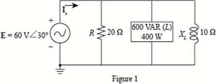
For the circuit of Fig. 20.55:
a. Find the average, reactive, and apparent power for the 20
b. Repeat part (a) for the 10
c. Find the total number of watts, volt-amperes reactive, volt-amperes, and power factor Fp.
d. Find the current Is.
Expert Solution & Answer
Want to see the full answer?
Check out a sample textbook solution
Students have asked these similar questions
For the network of Fig. 20.56:
a. Find Is.
b. Find the average power delivered to each element.
c. Find the reactive power for each element.
d. Find the apparent power for each element.
e. Find PT, QT, ST, and Fp for the system.
f. Sketch the power triangle.
Please answer all subpart either 100% dislike is ready please all subpart in short and clear handwriting or typing
Q20.
A 230 V, 50 Hz AC supply is applied to a coil of 0.16 H inductance and 6.5 Q resistance
connected in series with a capacitor. The power consumed by the circuit is 2.61 KW at
0.566 pf lagging. Estimate the following:
i. Current flowing through the circuit.
i.
Phase angle between current and voltage.
iii.
The value of the capacitor.
i.
Three identical coils connected in star, take a total power of 1.5 kW at a pf of 0.2 lagging from a 3-phase 400-V, 60 Hz line. Find the inductance of each coil.
Chapter 20 Solutions
Introductory Circuit Analysis (13th Edition)
Ch. 20 - For the battery of bulbs (purely resistive)...Ch. 20 - For the network of Fig. 20.49 : a. Find the...Ch. 20 - For the network of Fig. 20.50 : a. Determine the...Ch. 20 - For the system of Fig. 20.51 : a. Find the total...Ch. 20 - For the system of Fig. 20.52 : a. Find PT, QT. and...Ch. 20 - 6. For the system of Fig. 20.53 : a. Find PT, QT....Ch. 20 - For the network of Fig. 20.54 : a. Find the type...Ch. 20 - For the circuit of Fig. 20.55: a. Find the...Ch. 20 - For the network of Fig. 20.56 : a. Find Is. b....Ch. 20 - Repeat Problem 9 for the network of Fig. 20.57.
Ch. 20 - For the network of Fig. 20.58: a. Find the average...Ch. 20 - An electrical system is rated 10 kVA, 200 V at a...Ch. 20 - An electrical system is rated 5 kVA, 120 V, at a...Ch. 20 - For the system of Fig. 20.59: a. Find the total...Ch. 20 - Repeat Problem 14 for the system of Fig. 20.60.Ch. 20 - For the circuit of Fig. 20.61: Find the total...Ch. 20 - For the circuit of Fig. 20.62: Find the total...Ch. 20 - Prob. 18PCh. 20 - The load on a 120 V, 60 Hz supply is 5 kW...Ch. 20 - The loading of a factory on a 1000 V, 60 Hz system...Ch. 20 - a. A wattmeter is connected with its current coil...Ch. 20 - The voltage source in Fig. 20.64 delivers 660 VA...Ch. 20 - a. An air-core coil is connected to a 200 V, 60 Hz...Ch. 20 - a. The inductance of an air-core coil is 0.08 H....Ch. 20 - Using PSpice or Multisim, obtain a plot of...
Knowledge Booster


Learn more about
Need a deep-dive on the concept behind this application? Look no further. Learn more about this topic, electrical-engineering and related others by exploring similar questions and additional content below.Similar questions
- After studding the network answer the questions. 1. Find Is. 2. Find the current passing through the capacitor 3. Find the average power delivered to each element. 4. Find the reactive power for each element. 5. Find the apparent power for each element. 6. Find the total number of watts, volt-amperes reactive, and volt-amperes of the circuit. 7. Find the power factor for the system. 8. Sketch the power triangle. R E = 50 V Z60° 10 Ω 4 0 f = 60 Hzarrow_forwardQ20. A 230 V, 50 Hz ac supply is applied to a coil of 0.16 H inductance and 6.5 Q resistance connected in series with a capacitor. The power consumed by the circuit is 2.61 KW at 0.566 pf lagging. Estimate the following: i. Current flowing through the circuit. ii. Phase angle between current and voltage. Draw the phasor diagram iii. The value of the capacitorarrow_forward1. A motor load consists of a resistance of 6 Ohms in series with an inductance of 12 mH. Assume 120Vac, 60 Hz supply. a. What is the complex impedance of the load? b. What is the ac current through this load? c. What is theta, the angle between voltage and current through this load? d. What is the power factor? e. What capacitance should be added in parallel with this load to correct the power factor to 1? f. What is the current from the supply when the power factor is corrected?arrow_forward
- A resistor of 6 Ω, a capacitor of 300 μF and an inductor of 5 mH are connected in series. If an AC power supply of frequency 50 Hz and a maximum voltage of 5V is connected to this circuit, determine: a. impedance of the circuit.b. rms current.c. rms voltage across resistor, capacitor and inductor.d. phase angle between the current and the total voltage in the circuitarrow_forwardThe voltage applied to the metal grid of CRO is negative with respect to cathode. Select one: O True O False The sinusoidal current waveform having the maximum value of 30 A. then the R.M.S value is Three coils each having resistance of 29 0 are connected in star across 436 V. 50 Hz supply. Then the total power consumed is O 19665.10 W O 3784.66 W O 755.20 W O 226.05 Warrow_forwardA 5-ohm resistor is connected in series with a 25 micro-farad capacitor. A source voltage of 158 volts, 50 Hz supplies the combination. Determine the following: a. Circulating current b. Voltage across the resistor c. Voltage across the capacitor d. Real power supplied by the source e. Reactive power supplied by the source f. Apparent power of the circuit g. Power factor of the entire circuitarrow_forward
- A 30 Ω resistor and a reactor coil (inductor coil) with a 0.2 H inductance and negligible resistance are connected in series across a 120 V, 25 Hz supply. Determine: the impedance of the circuit. the current. the true power in watts taken by the circuit. the power factor. the phase anglearrow_forwardA. Find the average power absorbed by the load in the circuit. Use positive value if the power is absorbed and negative value if the power is delivered. B. Find the reactive power absorbed by the load. Use positive value if the reactive power is absorbed and negative value if the reactive power is delivered. C. Find the apparent power for the load.arrow_forward2-0-ea:: anc20Mass:c20Transter-conuştüru ci.pdf Dersler Z Zimbra Gelen Kutu.. C eemanonline.com.t. e Cağrı Merkezi 66% PREUMINARY INFORMATION: Electrical compensation is a major scale subject that every business/facility is Included. The power factor should be compensated to change the reactive power up to some specific values since some reactive power limits are not good for consumption and generation of the electricity (this is a far large topic which also forms some subbranches, for more information and specification please research yourself). For this reason, it is an obligation to use a compensator system for both manufacturers (wind farms/hydroelectric power plants/etc.) and consumers (residents/factories/etc.). These issues are regulated by official directives. EXERCISE STEPS: A single-phase load has an active power of P = 2 kW at 180 V @60HZ and the power factor is coso = 0.75. This motor is compensated to coso = 0.85 using a parallel capacitor (the load is modelled as series…arrow_forward
- Q-4: a) Calculate the values of R and C in the following circuit for maximum average power transfer to R. b) What is the maximum average power transferred to R? 100 Q 500/0° V w=100 rad/s CRarrow_forwardA series circuit composed of a 100 ohms resistor and a 20 microfarad capacitor connected across 240V, 60 HZ line. Calculate the voltage drop across the resistance. 144.50V 86.44V 200.65V 110.84Varrow_forwardFor a system with total complex power of 10000 + 7500j VA, nominal voltage of 250 angle 30 deg. and 50HZ system frequency. Vrms. When this system power factor is raised to power factor 0.9 leading. Determine the new current. 44.44 angle 55.84 deg. A 44.44 angle -55.84 deg. A 50 angle -66.87 deg. A 50 angle 66.87 deg. Aarrow_forward
arrow_back_ios
SEE MORE QUESTIONS
arrow_forward_ios
Recommended textbooks for you
 Introductory Circuit Analysis (13th Edition)Electrical EngineeringISBN:9780133923605Author:Robert L. BoylestadPublisher:PEARSON
 Delmar's Standard Textbook Of ElectricityElectrical EngineeringISBN:9781337900348Author:Stephen L. HermanPublisher:Cengage Learning
 Programmable Logic ControllersElectrical EngineeringISBN:9780073373843Author:Frank D. PetruzellaPublisher:McGraw-Hill Education
 Fundamentals of Electric CircuitsElectrical EngineeringISBN:9780078028229Author:Charles K Alexander, Matthew SadikuPublisher:McGraw-Hill Education
 Electric Circuits. (11th Edition)Electrical EngineeringISBN:9780134746968Author:James W. Nilsson, Susan RiedelPublisher:PEARSON
 Engineering ElectromagneticsElectrical EngineeringISBN:9780078028151Author:Hayt, William H. (william Hart), Jr, BUCK, John A.Publisher:Mcgraw-hill Education,
Introductory Circuit Analysis (13th Edition)
Electrical Engineering
ISBN:9780133923605
Author:Robert L. Boylestad
Publisher:PEARSON
Delmar's Standard Textbook Of Electricity
Electrical Engineering
ISBN:9781337900348
Author:Stephen L. Herman
Publisher:Cengage Learning
Programmable Logic Controllers
Electrical Engineering
ISBN:9780073373843
Author:Frank D. Petruzella
Publisher:McGraw-Hill Education
Fundamentals of Electric Circuits
Electrical Engineering
ISBN:9780078028229
Author:Charles K Alexander, Matthew Sadiku
Publisher:McGraw-Hill Education
Electric Circuits. (11th Edition)
Electrical Engineering
ISBN:9780134746968
Author:James W. Nilsson, Susan Riedel
Publisher:PEARSON
Engineering Electromagnetics
Electrical Engineering
ISBN:9780078028151
Author:Hayt, William H. (william Hart), Jr, BUCK, John A.
Publisher:Mcgraw-hill Education,
Inductors Explained - The basics how inductors work working principle; Author: The Engineering Mindset;https://www.youtube.com/watch?v=KSylo01n5FY;License: Standard Youtube License