
Introductory Circuit Analysis (13th Edition)
13th Edition
ISBN: 9780133923605
Author: Robert L. Boylestad
Publisher: PEARSON
expand_more
expand_more
format_list_bulleted
Concept explainers
Videos
Textbook Question
Chapter 20, Problem 9P
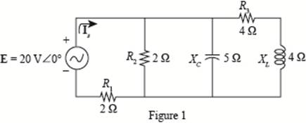
For the network of Fig. 20.56 :
a. Find Is.
b. Find the average power delivered to each element.
c. Find the reactive power for each element.
d. Find the apparent power for each element.
e. Find PT, QT, ST. and Fp for the system.
f. Sketch the power triangle.
Expert Solution & Answer
Want to see the full answer?
Check out a sample textbook solution
Students have asked these similar questions
After studding the network answer the questions.
1. Find Is.
2. Find the current passing through the capacitor
3. Find the average power delivered to each element.
4. Find the reactive power for each element.
5. Find the apparent power for each element.
6. Find the total number of watts, volt-amperes reactive, and volt-amperes of the circuit.
7. Find the power factor for the system.
8. Sketch the power triangle.
R
E = 50 V Z60°
10 Ω
4 0
f = 60 Hz
Use the image to answer the 3 part question.
A)determine the impedance of the circuit.
B)determine the average power provided by the source to the circuit.
C) Determine Vr the maximum voltage drop through the resistor and Vc max the maximum voltage drop through the capacitor
An alternating voltage of 110 volts is applied to a circuit with resistance of 8.66 Ohms,
inductance of 0.106 Henries, and capacitance of 75.8 microFarads. The frequency of
the voltage is 50 Hz. Determine:
a. The current in the circuit and its phase angle relative to the applied voltage.
b. The voltage drop across each component of the circuit.
c. The active and reactive power inputs to the circuit.
d. Draw (Not hand-sketch) the equivalent power triangle.
e. Is the RLC load of the circuit inductive or capacitive? Why?
Chapter 20 Solutions
Introductory Circuit Analysis (13th Edition)
Ch. 20 - For the battery of bulbs (purely resistive)...Ch. 20 - For the network of Fig. 20.49 : a. Find the...Ch. 20 - For the network of Fig. 20.50 : a. Determine the...Ch. 20 - For the system of Fig. 20.51 : a. Find the total...Ch. 20 - For the system of Fig. 20.52 : a. Find PT, QT. and...Ch. 20 - 6. For the system of Fig. 20.53 : a. Find PT, QT....Ch. 20 - For the network of Fig. 20.54 : a. Find the type...Ch. 20 - For the circuit of Fig. 20.55: a. Find the...Ch. 20 - For the network of Fig. 20.56 : a. Find Is. b....Ch. 20 - Repeat Problem 9 for the network of Fig. 20.57.
Ch. 20 - For the network of Fig. 20.58: a. Find the average...Ch. 20 - An electrical system is rated 10 kVA, 200 V at a...Ch. 20 - An electrical system is rated 5 kVA, 120 V, at a...Ch. 20 - For the system of Fig. 20.59: a. Find the total...Ch. 20 - Repeat Problem 14 for the system of Fig. 20.60.Ch. 20 - For the circuit of Fig. 20.61: Find the total...Ch. 20 - For the circuit of Fig. 20.62: Find the total...Ch. 20 - Prob. 18PCh. 20 - The load on a 120 V, 60 Hz supply is 5 kW...Ch. 20 - The loading of a factory on a 1000 V, 60 Hz system...Ch. 20 - a. A wattmeter is connected with its current coil...Ch. 20 - The voltage source in Fig. 20.64 delivers 660 VA...Ch. 20 - a. An air-core coil is connected to a 200 V, 60 Hz...Ch. 20 - a. The inductance of an air-core coil is 0.08 H....Ch. 20 - Using PSpice or Multisim, obtain a plot of...
Additional Engineering Textbook Solutions
Find more solutions based on key concepts
Assume a telephone signal travels through a cable at two-thirds the speed of light. How long does it take the s...
Electric Circuits (10th Edition)
The voltage source of the circuit shown in Fig. P1.29 is given by s(t)=25cos(4104t45)(V). Obtain an expression ...
Fundamentals of Applied Electromagnetics (7th Edition)
How many coulombs do 93.8 1016 electrons represent?
Principles Of Electric Circuits
Design an ideal inverting op-amp circuit such that the voltage gain is Av=25 . The maximum current in any resis...
Microelectronics: Circuit Analysis and Design
Three point charges of equal magnitude q, that will yield a zero net electric field at the origin.
Engineering Electromagnetics
When travelers from the USA and Canada visit Europe, they encounter a different power distribution system. Wall...
Electric machinery fundamentals
Knowledge Booster


Learn more about
Need a deep-dive on the concept behind this application? Look no further. Learn more about this topic, electrical-engineering and related others by exploring similar questions and additional content below.Similar questions
- A. Find the average power absorbed by the load in the circuit. Use positive value if the power is absorbed and negative value if the power is delivered. B. Find the reactive power absorbed by the load. Use positive value if the reactive power is absorbed and negative value if the reactive power is delivered. C. Find the apparent power for the load.arrow_forwarda-Calculate and draw the load current for the first two-period interval b-Calculate and draw the source current and find its average valuearrow_forward1) Determine the total current supplied by the source and the current in each branch. 2) Sketch a fully labelled phasor diagram showing all voltage and currents in the circuit. 3) Determine the active power delivered by the source voltage. 4) Determine the reactive power. 5) Sketch the power triangle. 6) Comment on the significance of the power factor and briefly state how it can be improved.arrow_forward
- i. Three identical coils connected in star, take a total power of 1.5 kW at a pf of 0.2 lagging from a 3-phase 400-V, 60 Hz line. Find the inductance of each coil.arrow_forwardProblem 4 An electric saw, a wood shaper, and a motor load of a workshop establish a 18 kVA power demand at 0.5 power factor lagging on a 208 V, 60 Hz supply. a) Establish the power triangle for the load. b) Determine the power-factor capacitor that must be place in parallel with the load to raise the power factor to 0.9 lagging. c) Determine the change in supply current from the uncompensated to the compensated system. d) Determine the power-factor capacitor that must be placed in parallel with the load to raise the power factor to unity.arrow_forwardA 5-ohm resistor is connected in series with a 25 micro-farad capacitor. A source voltage of 158 volts, 50 Hz supplies the combination. Determine the following: a. Circulating current b. Voltage across the resistor c. Voltage across the capacitor d. Real power supplied by the source e. Reactive power supplied by the source f. Apparent power of the circuit g. Power factor of the entire circuitarrow_forward
- 1. A motor load consists of a resistance of 6 Ohms in series with an inductance of 12 mH. Assume 120Vac, 60 Hz supply. a. What is the complex impedance of the load? b. What is the ac current through this load? c. What is theta, the angle between voltage and current through this load? d. What is the power factor? e. What capacitance should be added in parallel with this load to correct the power factor to 1? f. What is the current from the supply when the power factor is corrected?arrow_forwardThree impedances 10-j30 are connected in star across 100 volts 60 HZ Line to Neutral, Calculate a. PF of the load b. Line Current c. Active Power d. Apparent Powerarrow_forwardThe concentration ratio of parabolic trough power plant is typically O a. from 30 to 40 O b. more than 1500 O c. less than 10 O d. from 10 to 20arrow_forward
- AVERAGE POWER( NEED NEAT HANDWRITTEN SOLUTION ONLY OTHERWISE DOWNVOTE).arrow_forward2-0-ea:: anc20Mass:c20Transter-conuştüru ci.pdf Dersler Z Zimbra Gelen Kutu.. C eemanonline.com.t. e Cağrı Merkezi 66% PREUMINARY INFORMATION: Electrical compensation is a major scale subject that every business/facility is Included. The power factor should be compensated to change the reactive power up to some specific values since some reactive power limits are not good for consumption and generation of the electricity (this is a far large topic which also forms some subbranches, for more information and specification please research yourself). For this reason, it is an obligation to use a compensator system for both manufacturers (wind farms/hydroelectric power plants/etc.) and consumers (residents/factories/etc.). These issues are regulated by official directives. EXERCISE STEPS: A single-phase load has an active power of P = 2 kW at 180 V @60HZ and the power factor is coso = 0.75. This motor is compensated to coso = 0.85 using a parallel capacitor (the load is modelled as series…arrow_forwardif Pd exceeds Pg generation, what will be the effects on the frequency of the power systemsarrow_forward
arrow_back_ios
SEE MORE QUESTIONS
arrow_forward_ios
Recommended textbooks for you
 Introductory Circuit Analysis (13th Edition)Electrical EngineeringISBN:9780133923605Author:Robert L. BoylestadPublisher:PEARSON
 Delmar's Standard Textbook Of ElectricityElectrical EngineeringISBN:9781337900348Author:Stephen L. HermanPublisher:Cengage Learning
 Programmable Logic ControllersElectrical EngineeringISBN:9780073373843Author:Frank D. PetruzellaPublisher:McGraw-Hill Education
 Fundamentals of Electric CircuitsElectrical EngineeringISBN:9780078028229Author:Charles K Alexander, Matthew SadikuPublisher:McGraw-Hill Education
 Electric Circuits. (11th Edition)Electrical EngineeringISBN:9780134746968Author:James W. Nilsson, Susan RiedelPublisher:PEARSON
 Engineering ElectromagneticsElectrical EngineeringISBN:9780078028151Author:Hayt, William H. (william Hart), Jr, BUCK, John A.Publisher:Mcgraw-hill Education,
Introductory Circuit Analysis (13th Edition)
Electrical Engineering
ISBN:9780133923605
Author:Robert L. Boylestad
Publisher:PEARSON
Delmar's Standard Textbook Of Electricity
Electrical Engineering
ISBN:9781337900348
Author:Stephen L. Herman
Publisher:Cengage Learning
Programmable Logic Controllers
Electrical Engineering
ISBN:9780073373843
Author:Frank D. Petruzella
Publisher:McGraw-Hill Education
Fundamentals of Electric Circuits
Electrical Engineering
ISBN:9780078028229
Author:Charles K Alexander, Matthew Sadiku
Publisher:McGraw-Hill Education
Electric Circuits. (11th Edition)
Electrical Engineering
ISBN:9780134746968
Author:James W. Nilsson, Susan Riedel
Publisher:PEARSON
Engineering Electromagnetics
Electrical Engineering
ISBN:9780078028151
Author:Hayt, William H. (william Hart), Jr, BUCK, John A.
Publisher:Mcgraw-hill Education,
Current Divider Rule; Author: Neso Academy;https://www.youtube.com/watch?v=hRU1mKWUehY;License: Standard YouTube License, CC-BY