
Concept explainers
Videos
For the network of Fig. 20.58:
a. Find the average power delivered to each element.
b. Find the reactive power for each element.
c. Find the apparent power for each element.
d. Find the total number of watts, volt-amperes reactive, volt-amperes, and power factor Fp of the network.
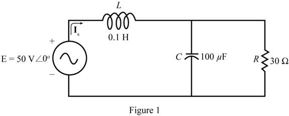
Fig. 20.58
e. Sketch the power triangle.
f. Find the energy dissipated by the resistor over one full cycle of the input voltage.
g. Find the energy stored or returned by the capacitor and the inductor over one half-cycle of the power curve for each.

Trending nowThis is a popular solution!

Chapter 20 Solutions
Introductory Circuit Analysis (13th Edition)
Additional Engineering Textbook Solutions
Electric Circuits. (11th Edition)
ELECTRICITY FOR TRADES (LOOSELEAF)
Electronics Fundamentals: Circuits, Devices & Applications
Programmable Logic Controllers
Electric Circuits (10th Edition)
Principles Of Electric Circuits


- A curve is drawm in descending order of load with time. Al1arrow_forward1.58 A single-phase ac voltage source has 200 V rms and a system connected consumes an active power of 300 W. What is the reactive power consumed by the system if 2.5 A rms current is drawn?arrow_forwardA 5-ohm resistor is connected in series with a 25 micro-farad capacitor. A source voltage of 158 volts, 50 Hz supplies the combination. Determine the following: a. Circulating current b. Voltage across the resistor c. Voltage across the capacitor d. Real power supplied by the source e. Reactive power supplied by the source f. Apparent power of the circuit g. Power factor of the entire circuitarrow_forward
- A. Find the average power absorbed by the load in the circuit. Use positive value if the power is absorbed and negative value if the power is delivered. B. Find the reactive power absorbed by the load. Use positive value if the reactive power is absorbed and negative value if the reactive power is delivered. C. Find the apparent power for the load.arrow_forwardAC electrical circuit is below: (refer picture below) a. Determine the current flowing in the load. b. If it is desired that the system power factor be 0.9. With system frequency = 50 Hz. Determine how large the capacitor is must be installed? Which one is correct? A/B/others answer A. C = 7.7015 mF B. C = 35.243 µF c. Please Draw all the phasor. Please give complete, details, and correct answer. Please do step by step, draw the phasor Please using handwriting (not typing ). THANK YOU, I WILL GIVE MANY THUMBS UP.arrow_forwardAn alternating voltage of 110 volts is applied to a circuit with resistance of 8.66 Ohms, inductance of 0.106 Henries, and capacitance of 75.8 microFarads. The frequency of the voltage is 50 Hz. Determine: a. The current in the circuit and its phase angle relative to the applied voltage. b. The voltage drop across each component of the circuit. c. The active and reactive power inputs to the circuit. d. Draw (Not hand-sketch) the equivalent power triangle. e. Is the RLC load of the circuit inductive or capacitive? Why?arrow_forward
- 1. Draw the waveform for Single Phase Power Supply and find the frequency if the time taken for 10 cycles is 10sec.arrow_forwardWhat is the standard frequency of electricity in sultanate of oman? O a. 120 Hz O b. 60 Hz O c. 100 Hz O d. 50 Hzarrow_forwardFor figure 3, how do I find: Is The average power delivered to each element, the reactive power for each element, & the apparent power for each element. Find PT, QT, ST, and Fp for the system. Sketch the power triangle.arrow_forward
- i. Three identical coils connected in star, take a total power of 1.5 kW at a pf of 0.2 lagging from a 3-phase 400-V, 60 Hz line. Find the inductance of each coil.arrow_forwardQ1: A 50HZ,11KV,3-ph,alternator with earthed neutral has a reactance of 50\ph and is connected to bus bar through a C.B.The distributed capacitance up to C.B between phase and neutral is 0.01HF,Determine: 1-The restriking voltage across the contacts of the breaker, 2-The frequency of oscillation,and 3-The voltage across the capacitance. (if the disconnecting capacitive tank)? Q2:Repeat (1,2,and 3) in Q1 if the P.F. of the fault was capacitance current breaking due to 0.4? Q3:Repeat (1,2,and 3) in Q1 if the current chops at an instantaneous rate of 8A?arrow_forward1. Determine the RMS values of voltage and current, and the total power absorbed by the circuit elementarrow_forward
 Introductory Circuit Analysis (13th Edition)Electrical EngineeringISBN:9780133923605Author:Robert L. BoylestadPublisher:PEARSON
 Delmar's Standard Textbook Of ElectricityElectrical EngineeringISBN:9781337900348Author:Stephen L. HermanPublisher:Cengage Learning
 Programmable Logic ControllersElectrical EngineeringISBN:9780073373843Author:Frank D. PetruzellaPublisher:McGraw-Hill Education
 Fundamentals of Electric CircuitsElectrical EngineeringISBN:9780078028229Author:Charles K Alexander, Matthew SadikuPublisher:McGraw-Hill Education
 Electric Circuits. (11th Edition)Electrical EngineeringISBN:9780134746968Author:James W. Nilsson, Susan RiedelPublisher:PEARSON
 Engineering ElectromagneticsElectrical EngineeringISBN:9780078028151Author:Hayt, William H. (william Hart), Jr, BUCK, John A.Publisher:Mcgraw-hill Education,