
Introductory Circuit Analysis (13th Edition)
13th Edition
ISBN: 9780133923605
Author: Robert L. Boylestad
Publisher: PEARSON
expand_more
expand_more
format_list_bulleted
Videos
Textbook Question
Chapter 20, Problem 21P
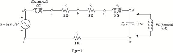
a. A wattmeter is connected with its current coil as shown in Fig. 20.63 and with the potential coil across points f-g. What does the wattmeter read?
b. Repeat part (a) with the potential coil (PC) across
Expert Solution & Answer
Want to see the full answer?
Check out a sample textbook solution
Students have asked these similar questions
1. Each phase of a delta-connected load comprises a resistor of 50 a and capacitor of 50 uF in
series. Calculate (a) the line and phase currents (b) the total power and (c) the kilovoltamperes when the
load is connected to a 440-V, 3-phase, 50-Hz supply.
2. Three similar-coils, A, B and C are available. Each coil has 9Q resistance and 12 Q reactance.
They are connected in delta to a 3-phase, 440-V, 50-Hz supply. Calculate for this load:
(a) the line cuIrent
(c) the total kilovolt-amperes
If the coils are reconnected in star, calculate for the new load the quantities named at (a), (b); (c) and
(d) above.
3. Three similar choke coils are connected in star to a 3-phase supply. If the line currents are 15 A,
the total power consumed is 11 kW and the volt-ampere input is 15 kVA, find the line and phase voltages,
the VAR input and the reactance and resistance of each coil.
[(a) 9.46 A; 5.46 A (b) 4480 W () 7.24 kVA]
(b) the power factor
(d) the total kilowatts
[50.7 A; 0.6; 38.6 kVA; 23.16…
2-0-ea:: anc20Mass:c20Transter-conuştüru ci.pdf
Dersler
Z Zimbra Gelen Kutu..
C eemanonline.com.t.
e Cağrı Merkezi
66%
PREUMINARY INFORMATION:
Electrical compensation is a major scale subject that every business/facility is Included. The power
factor should be compensated to change the reactive power up to some specific values since some
reactive power limits are not good for consumption and generation of the electricity (this is a far
large topic which also forms some subbranches, for more information and specification please
research yourself). For this reason, it is an obligation to use a compensator system for both
manufacturers (wind farms/hydroelectric power plants/etc.) and consumers
(residents/factories/etc.). These issues are regulated by official directives.
EXERCISE STEPS:
A single-phase load has an active power of P = 2 kW at 180 V @60HZ and the power factor is coso =
0.75. This motor is compensated to coso = 0.85 using a parallel capacitor (the load is modelled as
series…
PHASE DIFFERENCE FIND( NEED NEAT HANDWRITTEN SOLUTION ONLY OTHERWISE DOWNVOTE).
Chapter 20 Solutions
Introductory Circuit Analysis (13th Edition)
Ch. 20 - For the battery of bulbs (purely resistive)...Ch. 20 - For the network of Fig. 20.49 : a. Find the...Ch. 20 - For the network of Fig. 20.50 : a. Determine the...Ch. 20 - For the system of Fig. 20.51 : a. Find the total...Ch. 20 - For the system of Fig. 20.52 : a. Find PT, QT. and...Ch. 20 - 6. For the system of Fig. 20.53 : a. Find PT, QT....Ch. 20 - For the network of Fig. 20.54 : a. Find the type...Ch. 20 - For the circuit of Fig. 20.55: a. Find the...Ch. 20 - For the network of Fig. 20.56 : a. Find Is. b....Ch. 20 - Repeat Problem 9 for the network of Fig. 20.57.
Ch. 20 - For the network of Fig. 20.58: a. Find the average...Ch. 20 - An electrical system is rated 10 kVA, 200 V at a...Ch. 20 - An electrical system is rated 5 kVA, 120 V, at a...Ch. 20 - For the system of Fig. 20.59: a. Find the total...Ch. 20 - Repeat Problem 14 for the system of Fig. 20.60.Ch. 20 - For the circuit of Fig. 20.61: Find the total...Ch. 20 - For the circuit of Fig. 20.62: Find the total...Ch. 20 - Prob. 18PCh. 20 - The load on a 120 V, 60 Hz supply is 5 kW...Ch. 20 - The loading of a factory on a 1000 V, 60 Hz system...Ch. 20 - a. A wattmeter is connected with its current coil...Ch. 20 - The voltage source in Fig. 20.64 delivers 660 VA...Ch. 20 - a. An air-core coil is connected to a 200 V, 60 Hz...Ch. 20 - a. The inductance of an air-core coil is 0.08 H....Ch. 20 - Using PSpice or Multisim, obtain a plot of...
Knowledge Booster


Learn more about
Need a deep-dive on the concept behind this application? Look no further. Learn more about this topic, electrical-engineering and related others by exploring similar questions and additional content below.Similar questions
- Q20. A 230 V, 50 Hz AC supply is applied to a coil of 0.16 H inductance and 6.5 Q resistance connected in series with a capacitor. The power consumed by the circuit is 2.61 KW at 0.566 pf lagging. Estimate the following: i. Current flowing through the circuit. i. Phase angle between current and voltage. iii. The value of the capacitor.arrow_forwardA 5-ohm resistor is connected in series with a 25 micro-farad capacitor. A source voltage of 158 volts, 50 Hz supplies the combination. Determine the following: a. Circulating current b. Voltage across the resistor c. Voltage across the capacitor d. Real power supplied by the source e. Reactive power supplied by the source f. Apparent power of the circuit g. Power factor of the entire circuitarrow_forwardQ20. A 230 V, 50 Hz ac supply is applied to a coil of 0.16 H inductance and 6.5 Q resistance connected in series with a capacitor. The power consumed by the circuit is 2.61 KW at 0.566 pf lagging. Estimate the following: i. Current flowing through the circuit. ii. Phase angle between current and voltage. Draw the phasor diagram iii. The value of the capacitorarrow_forward
- Determine the maximum peak-to-peak ripple current of previous problem by using the next equations, and compare the results. DI. = max V R tanh R 4fL DI = V S max 4fLarrow_forwardUse 3 decimal places and box the final answer. A 4-ohm resistor is in series with a 7.96-mH inductor connected across a 110-V 60-Hz source. Determine : a) the impedance b) the input current c) the voltage across the resistor and the inductor d) Draw the phasor diagram showing the current and the voltages. e) The power factor and the power input to the circuit.arrow_forward7. Two coils are connected in series. With 2 A d.c. through the circuit, the p.ds. across the coils are 20 and 30 V respectively. With 2 A a.c. at 40 Hz, the p.ds. across the coils are 140 and 100 V respectively. If the two colls in series are connected to a 230-V, 50-Hz supply, całculate (a) the current (b) the power (c) the power factor,arrow_forward
- A 25-ohm resistor connected in series with a coil of 50-ohm resistance and 150-mH inductance. What is the power factor of the circuit? The standard frequency is 60 Hz. Show complete solution.arrow_forwardVariation of which of the following parameter is not consider as power quality problem for industry?VoltageCurrentPowerFrequencyarrow_forwardIn case RL load, it is desired to get an average load voltage of 75 V. Determine the firing angle if the ac supply voltage is 200V per phase. If the load resistance is 302, calculate the average load current and power. Design the thyristor. 4-arrow_forward
- 13. A circuit is composed of a resistance of 22 ohms, an inductance of 0.11 henry and a capacitance of 12 microfarad, all connected in parallel to a 115-volt 60-Hz supply. Calculate the power factor of the circuit 0.877 lagging 0.918 lagging 0.918 leading 0.877 leadingarrow_forwardWhat is the common frequency of alternating current in the United States? Select one: A. 25 HERTZ B. 50 HERTZ C. 60 HERTZ D. NONE OF THE ABOVEarrow_forward1. An electro-magnet draws 3 kW of active power and 4 kvar of reactive power. a. Calculate the apparent power. b. Calculate the power factor. 2. A capacitor drawing 4 kvar is placed in parallel with the electro-magnet of Question 1. a. Calculate the new value of apparent power b. What is the new value of reactive power? c. What is the value of active power? d. What is the new power factor?arrow_forward
arrow_back_ios
SEE MORE QUESTIONS
arrow_forward_ios
Recommended textbooks for you
 Introductory Circuit Analysis (13th Edition)Electrical EngineeringISBN:9780133923605Author:Robert L. BoylestadPublisher:PEARSON
 Delmar's Standard Textbook Of ElectricityElectrical EngineeringISBN:9781337900348Author:Stephen L. HermanPublisher:Cengage Learning
 Programmable Logic ControllersElectrical EngineeringISBN:9780073373843Author:Frank D. PetruzellaPublisher:McGraw-Hill Education
 Fundamentals of Electric CircuitsElectrical EngineeringISBN:9780078028229Author:Charles K Alexander, Matthew SadikuPublisher:McGraw-Hill Education
 Electric Circuits. (11th Edition)Electrical EngineeringISBN:9780134746968Author:James W. Nilsson, Susan RiedelPublisher:PEARSON
 Engineering ElectromagneticsElectrical EngineeringISBN:9780078028151Author:Hayt, William H. (william Hart), Jr, BUCK, John A.Publisher:Mcgraw-hill Education,
Introductory Circuit Analysis (13th Edition)
Electrical Engineering
ISBN:9780133923605
Author:Robert L. Boylestad
Publisher:PEARSON
Delmar's Standard Textbook Of Electricity
Electrical Engineering
ISBN:9781337900348
Author:Stephen L. Herman
Publisher:Cengage Learning
Programmable Logic Controllers
Electrical Engineering
ISBN:9780073373843
Author:Frank D. Petruzella
Publisher:McGraw-Hill Education
Fundamentals of Electric Circuits
Electrical Engineering
ISBN:9780078028229
Author:Charles K Alexander, Matthew Sadiku
Publisher:McGraw-Hill Education
Electric Circuits. (11th Edition)
Electrical Engineering
ISBN:9780134746968
Author:James W. Nilsson, Susan Riedel
Publisher:PEARSON
Engineering Electromagnetics
Electrical Engineering
ISBN:9780078028151
Author:Hayt, William H. (william Hart), Jr, BUCK, John A.
Publisher:Mcgraw-hill Education,
Inductors Explained - The basics how inductors work working principle; Author: The Engineering Mindset;https://www.youtube.com/watch?v=KSylo01n5FY;License: Standard Youtube License