
Introductory Circuit Analysis (13th Edition)
13th Edition
ISBN: 9780133923605
Author: Robert L. Boylestad
Publisher: PEARSON
expand_more
expand_more
format_list_bulleted
Concept explainers
Videos
Textbook Question
Chapter 20, Problem 5P
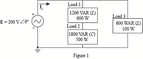
For the system of Fig. 20.52 :
a. Find PT, QT. and ST.
b. Determine the power factor Fp.
c. Draw the power triangle.
d. Find ls
Expert Solution & Answer
Want to see the full answer?
Check out a sample textbook solution
Students have asked these similar questions
2. For the full-wave rectifier, the source is a sinusoid with values presented in Fig. 2.
The component parameters are:
Vmax = √2 x 110 V
frequency = 60 Hz
Z=17Ω
Determine:
a. Average voltage across the load.
b. Average voltage across the source.
c. Average load current.
d.
RMS voltage of the load.
RMS current of the load.
Power consumed by the load.
e.
f.
D
A
Du
주
Vs (t)
is (t)
C
6
D3
D₂
it (t)
Z
V₁ (t)
1. For the half-wave rectifier, the source is a sinusoid with the values presented in Fig. 1.
The component parameters are:
Vmax = √2 x 100 V
frequency = 60 Hz
R = 12.5 2
Determine:
a. Average voltage across the load.
b. Average voltage across the source.
c. Average load current.
d.
e.
RMS voltage of the load.
RMS current of the load.
Power consumed by the load.
Power factor of the circuit.
h. Efficiency of the circuit.
g.
V₁= Vmax sin (wt)
Vd
ܝܡ*
R.
+
1
1.Find the following:
a.ZT
b.I2
c.Vr
d.Vo
e.Pt (total power)
f.Fp (power factor)
Chapter 20 Solutions
Introductory Circuit Analysis (13th Edition)
Ch. 20 - For the battery of bulbs (purely resistive)...Ch. 20 - For the network of Fig. 20.49 : a. Find the...Ch. 20 - For the network of Fig. 20.50 : a. Determine the...Ch. 20 - For the system of Fig. 20.51 : a. Find the total...Ch. 20 - For the system of Fig. 20.52 : a. Find PT, QT. and...Ch. 20 - 6. For the system of Fig. 20.53 : a. Find PT, QT....Ch. 20 - For the network of Fig. 20.54 : a. Find the type...Ch. 20 - For the circuit of Fig. 20.55: a. Find the...Ch. 20 - For the network of Fig. 20.56 : a. Find Is. b....Ch. 20 - Repeat Problem 9 for the network of Fig. 20.57.
Ch. 20 - For the network of Fig. 20.58: a. Find the average...Ch. 20 - An electrical system is rated 10 kVA, 200 V at a...Ch. 20 - An electrical system is rated 5 kVA, 120 V, at a...Ch. 20 - For the system of Fig. 20.59: a. Find the total...Ch. 20 - Repeat Problem 14 for the system of Fig. 20.60.Ch. 20 - For the circuit of Fig. 20.61: Find the total...Ch. 20 - For the circuit of Fig. 20.62: Find the total...Ch. 20 - Prob. 18PCh. 20 - The load on a 120 V, 60 Hz supply is 5 kW...Ch. 20 - The loading of a factory on a 1000 V, 60 Hz system...Ch. 20 - a. A wattmeter is connected with its current coil...Ch. 20 - The voltage source in Fig. 20.64 delivers 660 VA...Ch. 20 - a. An air-core coil is connected to a 200 V, 60 Hz...Ch. 20 - a. The inductance of an air-core coil is 0.08 H....Ch. 20 - Using PSpice or Multisim, obtain a plot of...
Additional Engineering Textbook Solutions
Find more solutions based on key concepts
For the “tank” circuit in Fig. 14.79, find the resonant frequency.
Figure 14.79
For Probs. 14.39, 14.71, and 1...
Fundamentals of Electric Circuits
Explain the main function of each of the following major components of a PLC: a. Processor module (CPU) b. I/O ...
Programmable Logic Controllers
Analog Voltmeter Design Figure P2-98(a) shows a voltmeter circuit consisting of a D'Arsonval meter, two series ...
ANALYSIS+DESIGN OF LINEAR CIRCUITS(LL)
Find I0 and I1 in the circuit in Fig.P2.12.
Basic Engineering Circuit Analysis
The voltage source of the circuit shown in Fig. P1.29 is given by s(t)=25cos(4104t45)(V). Obtain an expression ...
Fundamentals of Applied Electromagnetics (7th Edition)
Design an ideal inverting op-amp circuit such that the voltage gain is Av=25 . The maximum current in any resis...
Microelectronics: Circuit Analysis and Design
Knowledge Booster


Learn more about
Need a deep-dive on the concept behind this application? Look no further. Learn more about this topic, electrical-engineering and related others by exploring similar questions and additional content below.Similar questions
- Please show your solution on a paper. with FBD.arrow_forwardProblem 02.005 - Nodes, Branches, and Loops For the network graph shown in the given figure, find the number of nodes, branches, and independent loops. A The number of nodes present in the given network graph is The number of branches present in the given network graph is The number of independent loops present in the given network graph isarrow_forwardASAP PLS Compute in Detail and then Draw the Power Triangle.arrow_forward
- Q2 Determine the currently in figure shown by using Nodal analysis method. 20 30 40 19 SA 20 BVarrow_forwardA For the eircuit shown Derive the equation for the resonmunt freguny? Ans: Ws- Lcarrow_forwardFind the currents in each of the resiston in fig 7 I-SA de 32. 722 www 12.01 f887 C 25.0. 6 42arrow_forward
- When the waveform shown in fig. (1) is applied to true responding ac voltmeter, the output would be (5.314 V). If the same signal is applied to average responding ac voltmeter, what will be: 1. The indicate value. 2. The true value. 3. The true form factor. 4. The indicate crest factor.arrow_forwardFor the network of Fig. 20.56: a. Find Is. b. Find the average power delivered to each element. c. Find the reactive power for each element. d. Find the apparent power for each element. e. Find PT, QT, ST, and Fp for the system. f. Sketch the power triangle. Please answer all subpart either 100% dislike is ready please all subpart in short and clear handwriting or typingarrow_forwardPls show the complete solution. Thank youarrow_forward
arrow_back_ios
SEE MORE QUESTIONS
arrow_forward_ios
Recommended textbooks for you
 Introductory Circuit Analysis (13th Edition)Electrical EngineeringISBN:9780133923605Author:Robert L. BoylestadPublisher:PEARSON
 Delmar's Standard Textbook Of ElectricityElectrical EngineeringISBN:9781337900348Author:Stephen L. HermanPublisher:Cengage Learning
 Programmable Logic ControllersElectrical EngineeringISBN:9780073373843Author:Frank D. PetruzellaPublisher:McGraw-Hill Education
 Fundamentals of Electric CircuitsElectrical EngineeringISBN:9780078028229Author:Charles K Alexander, Matthew SadikuPublisher:McGraw-Hill Education
 Electric Circuits. (11th Edition)Electrical EngineeringISBN:9780134746968Author:James W. Nilsson, Susan RiedelPublisher:PEARSON
 Engineering ElectromagneticsElectrical EngineeringISBN:9780078028151Author:Hayt, William H. (william Hart), Jr, BUCK, John A.Publisher:Mcgraw-hill Education,
Introductory Circuit Analysis (13th Edition)
Electrical Engineering
ISBN:9780133923605
Author:Robert L. Boylestad
Publisher:PEARSON
Delmar's Standard Textbook Of Electricity
Electrical Engineering
ISBN:9781337900348
Author:Stephen L. Herman
Publisher:Cengage Learning
Programmable Logic Controllers
Electrical Engineering
ISBN:9780073373843
Author:Frank D. Petruzella
Publisher:McGraw-Hill Education
Fundamentals of Electric Circuits
Electrical Engineering
ISBN:9780078028229
Author:Charles K Alexander, Matthew Sadiku
Publisher:McGraw-Hill Education
Electric Circuits. (11th Edition)
Electrical Engineering
ISBN:9780134746968
Author:James W. Nilsson, Susan Riedel
Publisher:PEARSON
Engineering Electromagnetics
Electrical Engineering
ISBN:9780078028151
Author:Hayt, William H. (william Hart), Jr, BUCK, John A.
Publisher:Mcgraw-hill Education,
Demos: Dielectric breakdown; Author: Caltech's Feynman Lecture Hall;https://www.youtube.com/watch?v=2YrHh1ikefI;License: Standard Youtube License