
Microelectronics: Circuit Analysis and Design
4th Edition
ISBN: 9780073380643
Author: Donald A. Neamen
Publisher: McGraw-Hill Companies, The
expand_more
expand_more
format_list_bulleted
Concept explainers
Videos
Textbook Question
Chapter 2, Problem 2.18P
(a) Sketch
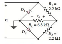
Figure P2.18
Expert Solution & Answer
Want to see the full answer?
Check out a sample textbook solution
Students have asked these similar questions
A.
The value of:
A=5 ms
C= 15 ms
Peak to peak = 10
B
D
Figure 1
(a)
From Figure 1 above, identify the frequency (f), value of time at A, B, C, D, period (T)
and the RMS.
Q2) A 3-phase, half-wave thyristor converter is connected through a voltage source 150 V as input voltage
and used to supply resistive load of 10 2. Determine rsm voltage, rms current, ripple factor and
dissipated power in the resistor R. If a = 45° and f = 50 Hz.
%3D
Q18. An AC waveform is shown in figure B3.
4
10
20
30
40
50
70
100
Time (ms)
110
-2
-3
-4
-5
Figure B3
i)
For the above waveform, determine
a. Peak-to-peak voltage
b. Time period
c. Frequency
ii)
For the above waveform, determine
a. Peak Factor
b. Form Factor
Chapter 2 Solutions
Microelectronics: Circuit Analysis and Design
Ch. 2 - Repeat Example 2.1 if the input voltage is...Ch. 2 - Consider the bridge circuit shown in Figure 2.6(a)...Ch. 2 - Assume the input signal to a rectifier circuit has...Ch. 2 - The input voltage to the halfwave rectifier in...Ch. 2 - Consider the circuit in Figure 2.4. The input...Ch. 2 - The circuit in Figure 2.5(a) is used to rectify a...Ch. 2 - The secondary transformer voltage of the rectifier...Ch. 2 - Determine the fraction (percent) of the cycle that...Ch. 2 - The Zener diode regulator circuit shown in Figure...Ch. 2 - Repeat Example 2.6 for rz=4 . Assume all other...
Ch. 2 - Consider the circuit shown in Figure 2.19. Let...Ch. 2 - Suppose the currentlimiting resistor in Example...Ch. 2 - Suppose the power supply voltage in the circuit...Ch. 2 - Design a parallelbased clipper that will yield the...Ch. 2 - Sketch the steadystate output voltage for the...Ch. 2 - Consider the circuit in Figure 2.23(a). Let R1=5k...Ch. 2 - Determine the steadystate output voltage O for the...Ch. 2 - Design a parallelbased clipper circuit that will...Ch. 2 - Consider the circuit shown in Figure 2.38, in...Ch. 2 - Consider the circuit shown in Figure 2.39. The...Ch. 2 - Repeat Example 2.11 for the case when R1=8k ,...Ch. 2 - The cutin voltage of each diode in the circuit...Ch. 2 - Prob. 2.12TYUCh. 2 - Consider the OR logic circuit shown in Figure...Ch. 2 - Consider the AND logic circuit shown in Figure...Ch. 2 - (a) Photons with an energy of hv=2eV are incident...Ch. 2 - Determine the value of resistance R required to...Ch. 2 - What characteristic of a diode is used in the...Ch. 2 - Prob. 2RQCh. 2 - Describe a simple fullwave diode rectifier circuit...Ch. 2 - Prob. 4RQCh. 2 - Prob. 5RQCh. 2 - Describe a simple Zener diode voltage reference...Ch. 2 - What effect does the Zener diode resistance have...Ch. 2 - What are the general characteristics of diode...Ch. 2 - Describe a simple diode clipper circuit that...Ch. 2 - Prob. 10RQCh. 2 - What one circuit element, besides a diode, is...Ch. 2 - Prob. 12RQCh. 2 - Describe a diode OR logic circuit. Compare a logic...Ch. 2 - Describe a diode AND logic circuit. Compare a...Ch. 2 - Describe a simple circuit that can be used to turn...Ch. 2 - Consider the circuit shown in Figure P2.1. Let...Ch. 2 - For the circuit shown in Figure P2.1, show that...Ch. 2 - A halfwave rectifier such as shown in Figure...Ch. 2 - Consider the battery charging circuit shown in...Ch. 2 - Figure P2.5 shows a simple fullwave battery...Ch. 2 - The fullwave rectifier circuit shown in Figure...Ch. 2 - The input signal voltage to the fullwave rectifier...Ch. 2 - The output resistance of the fullwave rectifier in...Ch. 2 - Repeat Problem 2.8 for the halfwave rectifier in...Ch. 2 - Consider the halfwave rectifier circuit shown in...Ch. 2 - The parameters of the halfwave rectifier circuit...Ch. 2 - The fullwave rectifier circuit shown in Figure...Ch. 2 - Consider the fullwave rectifier circuit in Figure...Ch. 2 - The circuit in Figure P2.14 is a complementary...Ch. 2 - Prob. 2.15PCh. 2 - A fullwave rectifier is to be designed using the...Ch. 2 - Prob. 2.17PCh. 2 - (a) Sketch o versus time for the circuit in Figure...Ch. 2 - Consider the circuit shown in Figure P2.19. The...Ch. 2 - Consider the Zener diode circuit shown in Figure...Ch. 2 - Consider the Zener diode circuit shown in Figure...Ch. 2 - In the voltage regulator circuit in Figure P2.21,...Ch. 2 - A Zener diode is connected in a voltage regulator...Ch. 2 - Consider the Zener diode circuit in Figure 2.19 in...Ch. 2 - Design a voltage regulator circuit such as shown...Ch. 2 - The percent regulation of the Zener diode...Ch. 2 - A voltage regulator is to have a nominal output...Ch. 2 - Consider the circuit in Figure P2.28. Let V=0 ....Ch. 2 - The secondary voltage in the circuit in Figure...Ch. 2 - The parameters in the circuit shown in Figure...Ch. 2 - Consider the circuit in Figure P2.31. Let V=0 (a)...Ch. 2 - Prob. 2.32PCh. 2 - Each diode cutin voltage is 0.7 V for the circuits...Ch. 2 - The diode in the circuit of Figure P2.34(a) has...Ch. 2 - Consider the circuits shown in Figure P2.35. Each...Ch. 2 - Plot O for each circuit in Figure P2.36 for the...Ch. 2 - Consider the parallel clipper circuit in Figure...Ch. 2 - A car’s radio may be subjected to voltage spikes...Ch. 2 - Sketch the steadystate output voltage O versus...Ch. 2 - Prob. D2.40PCh. 2 - Design a diode clamper to generate a steadystate...Ch. 2 - For the circuit in Figure P2.39(b), let V=0 and...Ch. 2 - Repeat Problem 2.42 for the circuit in Figure...Ch. 2 - The diodes in the circuit in Figure P2.44 have...Ch. 2 - In the circuit in Figure P2.45 the diodes have the...Ch. 2 - The diodes in the circuit in Figure P2.46 have the...Ch. 2 - Consider the circuit shown in Figure P2.47. Assume...Ch. 2 - The diode cutin voltage for each diode in the...Ch. 2 - Consider the circuit in Figure P2.49. Each diode...Ch. 2 - Assume V=0.7V for each diode in the circuit in...Ch. 2 - The cutin voltage of each diode in the circuit...Ch. 2 - Let V=0.7V for each diode in the circuit in Figure...Ch. 2 - For the circuit shown in Figure P2.54, let V=0.7V...Ch. 2 - Assume each diode cutin voltage is V=0.7V for the...Ch. 2 - If V=0.7V for the diode in the circuit in Figure...Ch. 2 - Let V=0.7V for the diode in the circuit in Figure...Ch. 2 - Each diode cutin voltage in the circuit in Figure...Ch. 2 - Let V=0.7V for each diode in the circuit shown in...Ch. 2 - Consider the circuit in Figure P2.61. The output...Ch. 2 - Consider the circuit in Figure P2.62. The output...Ch. 2 - Prob. 2.63PCh. 2 - Consider the circuit shown in Figure P2.64. The...Ch. 2 - The lightemitting diode in the circuit shown in...Ch. 2 - The parameters of D1 and D2 in the circuit shown...Ch. 2 - If the resistor in Example 2.12 is R=2 and the...Ch. 2 - Consider the photodiode circuit shown in Figure...Ch. 2 - Consider the fullwave bridge rectifier circuit....Ch. 2 - Design a simple dc voltage source using a...Ch. 2 - A clipper is to be designed such that O=2.5V for...Ch. 2 - Design a circuit to provide the voltage transfer...
Knowledge Booster


Learn more about
Need a deep-dive on the concept behind this application? Look no further. Learn more about this topic, electrical-engineering and related others by exploring similar questions and additional content below.Similar questions
- A generator rated at 30MVA, 11kV has a reactance of 40%. Calculate its p.u. reactances for a base of 50MVA and 10kV. O 0.606 p.u. O 0.506 p.u. O 0.806 p.u. O 0.706 p.u.arrow_forward5. Determine the impedance of the circuit of Figure 2.7.3 for a 1 kHz sine. I want to show all workarrow_forwardFor the network shown in figure (3), if the switch is closed for 2usec and then opened for Susec, find mathematical expressions for vi and in of both periods of time and then plot the waveforms of vL and i as a function of time.arrow_forward
- AC 15. What would the equivalent resistance be of a 159 uF capacitor? 16. What is the RMS voltage of a circuit if the peak voltage is 170 volts? 17. If the RMS voltage is 240 volts AC, what is the peak voltage? 18. What is the formula for finding an inductors equivalent resistance? 19. What is the equivalent resistance of an inductor with 0.17 henrys? 20. What is the symbol of an AC power source? 21. What is the equivalent inductance of a parallel circuit with a 0.01L, 0.02L, and 1.7L inductor? 22. What is the equivalent inductance of a series circuit with a 0.03L, 0.04L, and 1.6L inductor? 23. A transformer with a primary voltage of 480 volts and a turns ratio of 2:1 will have what secondary voltage? 24. A Power Network is comprised of what three components? 25. What is the main difference between a fuse and a circuit breaker?arrow_forwardGiven the circuit in Figure 04 and defining that: Vs = 100 sin (wt) Volts and the firing angle of the thyristors T1 and T2 is equal to 110° and that T3 and T4 have similar firings in the negative half-cycle of Vs. a)Sketch the output voltage waveform for a highly inductive load. b) Sketch the waveform output voltage, replacing the highly inductive load with a purely resistive load. c) Get the value of the average output voltage when the load is purely resistive.arrow_forwardQ1. Referring to the Figure Q1, answer the following questions: VI V1(wt) 40 V V(ot) 20 V Vm1 Vm 10 A i(ot) Im Reference( 0°) 30 80° i) The maximum and effective (rms) values of v(wt), v1(wt) and i(wt). ii) Write the waveform equations of v(wt), v1(wt) and i(wt). iii) Determine the phase relationship between the voltage, v1(wt) and the current, i(wt) and draw the phasor diagram. iv) Determine the impedance from Q1 (iii).arrow_forward
- 3. A sinusoidal waveform is displayed on a c.r.o. screen. The peak-to-peak distance is 5 cm and the distance between cycles is 4 cm. The 'time'switch is on 100 µs/cm and the 'volts/cm' switch is on 10 V/cm. Determine (i) angular frequency (ii) peak (iii) rms value of voltages (iv)Time period and (v) form factor.arrow_forward3. A sinusoidal waveform is displayed on a c.r.o. screen. The peak-to-peak distance is 5 cm and the distance between cycles is 4 cm. The 'time ' switch is on 100 µs/cm and the 'volts/cm' switch is on 10 V/cm. Determine (i) angular frequency (ii) peak (iii) rms value of voltages (iv)Time period and (v) form factor.arrow_forward1-Choose the correct statement for pure resistor connected across single phase AC supply. a. Current and Voltage are in phase b. Current leads the supply voltage by 90° c. None of these d. Current lags the supply voltage by 90° 2-Identify the current through the inductor in a RL transient circuit connected across DC voltage, when the switch is kept open. a. 0 b. Infinity c. V/R d. 1arrow_forward
- Determine the value that the unknown emf (E) must have so that the potential V12 = 9varrow_forward2. Build the circuit below shown in Figure 2. R1 1k V1 VOFF = 0 VAMPL = 4W FREQ = 10kHz C1 0.1uF Figure 2 2.3 Plot the waveform v for the voltage across R in simulation. Save the waveform and add it 2.4 Assuming the waveform of the voltage drop across R1 is Vr= VrPCOSwt, determine the amplitude (VRP, in 'Volt') and the radian frequency (w, in 'rad/sec') from the waveform.arrow_forwardFind the margin of K to keep the system shown in figure N°1 stablearrow_forward
arrow_back_ios
SEE MORE QUESTIONS
arrow_forward_ios
Recommended textbooks for you
 Introductory Circuit Analysis (13th Edition)Electrical EngineeringISBN:9780133923605Author:Robert L. BoylestadPublisher:PEARSON
 Delmar's Standard Textbook Of ElectricityElectrical EngineeringISBN:9781337900348Author:Stephen L. HermanPublisher:Cengage Learning
 Programmable Logic ControllersElectrical EngineeringISBN:9780073373843Author:Frank D. PetruzellaPublisher:McGraw-Hill Education
 Fundamentals of Electric CircuitsElectrical EngineeringISBN:9780078028229Author:Charles K Alexander, Matthew SadikuPublisher:McGraw-Hill Education
 Electric Circuits. (11th Edition)Electrical EngineeringISBN:9780134746968Author:James W. Nilsson, Susan RiedelPublisher:PEARSON
 Engineering ElectromagneticsElectrical EngineeringISBN:9780078028151Author:Hayt, William H. (william Hart), Jr, BUCK, John A.Publisher:Mcgraw-hill Education,
Introductory Circuit Analysis (13th Edition)
Electrical Engineering
ISBN:9780133923605
Author:Robert L. Boylestad
Publisher:PEARSON
Delmar's Standard Textbook Of Electricity
Electrical Engineering
ISBN:9781337900348
Author:Stephen L. Herman
Publisher:Cengage Learning
Programmable Logic Controllers
Electrical Engineering
ISBN:9780073373843
Author:Frank D. Petruzella
Publisher:McGraw-Hill Education
Fundamentals of Electric Circuits
Electrical Engineering
ISBN:9780078028229
Author:Charles K Alexander, Matthew Sadiku
Publisher:McGraw-Hill Education
Electric Circuits. (11th Edition)
Electrical Engineering
ISBN:9780134746968
Author:James W. Nilsson, Susan Riedel
Publisher:PEARSON
Engineering Electromagnetics
Electrical Engineering
ISBN:9780078028151
Author:Hayt, William H. (william Hart), Jr, BUCK, John A.
Publisher:Mcgraw-hill Education,
Types of Energy for Kids - Renewable and Non-Renewable Energies; Author: Smile and Learn - English;https://www.youtube.com/watch?v=w16-Uems2Qo;License: Standard Youtube License