
Microelectronics: Circuit Analysis and Design
4th Edition
ISBN: 9780073380643
Author: Donald A. Neamen
Publisher: McGraw-Hill Companies, The
expand_more
expand_more
format_list_bulleted
Videos
Textbook Question
Chapter 2, Problem 2.31P
Consider the circuit in Figure P2.31. Let
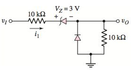
Figure P2.31
Expert Solution & Answer
Want to see the full answer?
Check out a sample textbook solution
Students have asked these similar questions
Q2 (a) Figure Q2(a) shows a clipper circuit made with a gemanium diode. Given the voltage
input, Vin = 20 Vp-p, VDc = 5 V, Rs = 10N and RL=1 kN.
(i)
Sketch the full cycle of input voltage, Vin(t) in sinusoidal waveform.
(ii)
Determine the output voltage values for all input values. Show all the calculations
and support your answers with the aid of diagram.
R.
Vin
Si
Ge
R
VOUT
Vpc
Figure Q2(a)
V1
R1
Da
S
Hill
Db
KH
R2
+
V3
I
Given that R1=2k, R2=1k, and Da and Db are
Si Diodes:
a. When will Da conduct with respect to V1?
b. When will Db conduct with respect to V1?
c. When will both Da and Db not conduct?
Q2) Find the Performance Parameters of a Full-Wave Rectifier with an
RL Load, the single-phase full-wave rectifier of the figure below has L = 6.5
mH, R = 2.52 and E= 10 V. The input voltage is Vs = 120 V at 60 Hz. Assume
that the load current is continuous current. Where:
V
io (t) = -(sin(wt - 0)+
im
Z
2
-R
1-ewr
-sin 8.e *)
E
R
Determine:
(1) The steady-state load current lo at wt = 0,
(2) The average diode current Ip(av),
(3) The rms diode current Ip(ms),
(4) The rms output current lo(ms), and
(5) The input power factor PF
D₁ D₂ A
Pa D₂ A
+
Vo
1.
E
Chapter 2 Solutions
Microelectronics: Circuit Analysis and Design
Ch. 2 - Repeat Example 2.1 if the input voltage is...Ch. 2 - Consider the bridge circuit shown in Figure 2.6(a)...Ch. 2 - Assume the input signal to a rectifier circuit has...Ch. 2 - The input voltage to the halfwave rectifier in...Ch. 2 - Consider the circuit in Figure 2.4. The input...Ch. 2 - The circuit in Figure 2.5(a) is used to rectify a...Ch. 2 - The secondary transformer voltage of the rectifier...Ch. 2 - Determine the fraction (percent) of the cycle that...Ch. 2 - The Zener diode regulator circuit shown in Figure...Ch. 2 - Repeat Example 2.6 for rz=4 . Assume all other...
Ch. 2 - Consider the circuit shown in Figure 2.19. Let...Ch. 2 - Suppose the currentlimiting resistor in Example...Ch. 2 - Suppose the power supply voltage in the circuit...Ch. 2 - Design a parallelbased clipper that will yield the...Ch. 2 - Sketch the steadystate output voltage for the...Ch. 2 - Consider the circuit in Figure 2.23(a). Let R1=5k...Ch. 2 - Determine the steadystate output voltage O for the...Ch. 2 - Design a parallelbased clipper circuit that will...Ch. 2 - Consider the circuit shown in Figure 2.38, in...Ch. 2 - Consider the circuit shown in Figure 2.39. The...Ch. 2 - Repeat Example 2.11 for the case when R1=8k ,...Ch. 2 - The cutin voltage of each diode in the circuit...Ch. 2 - Prob. 2.12TYUCh. 2 - Consider the OR logic circuit shown in Figure...Ch. 2 - Consider the AND logic circuit shown in Figure...Ch. 2 - (a) Photons with an energy of hv=2eV are incident...Ch. 2 - Determine the value of resistance R required to...Ch. 2 - What characteristic of a diode is used in the...Ch. 2 - Prob. 2RQCh. 2 - Describe a simple fullwave diode rectifier circuit...Ch. 2 - Prob. 4RQCh. 2 - Prob. 5RQCh. 2 - Describe a simple Zener diode voltage reference...Ch. 2 - What effect does the Zener diode resistance have...Ch. 2 - What are the general characteristics of diode...Ch. 2 - Describe a simple diode clipper circuit that...Ch. 2 - Prob. 10RQCh. 2 - What one circuit element, besides a diode, is...Ch. 2 - Prob. 12RQCh. 2 - Describe a diode OR logic circuit. Compare a logic...Ch. 2 - Describe a diode AND logic circuit. Compare a...Ch. 2 - Describe a simple circuit that can be used to turn...Ch. 2 - Consider the circuit shown in Figure P2.1. Let...Ch. 2 - For the circuit shown in Figure P2.1, show that...Ch. 2 - A halfwave rectifier such as shown in Figure...Ch. 2 - Consider the battery charging circuit shown in...Ch. 2 - Figure P2.5 shows a simple fullwave battery...Ch. 2 - The fullwave rectifier circuit shown in Figure...Ch. 2 - The input signal voltage to the fullwave rectifier...Ch. 2 - The output resistance of the fullwave rectifier in...Ch. 2 - Repeat Problem 2.8 for the halfwave rectifier in...Ch. 2 - Consider the halfwave rectifier circuit shown in...Ch. 2 - The parameters of the halfwave rectifier circuit...Ch. 2 - The fullwave rectifier circuit shown in Figure...Ch. 2 - Consider the fullwave rectifier circuit in Figure...Ch. 2 - The circuit in Figure P2.14 is a complementary...Ch. 2 - Prob. 2.15PCh. 2 - A fullwave rectifier is to be designed using the...Ch. 2 - Prob. 2.17PCh. 2 - (a) Sketch o versus time for the circuit in Figure...Ch. 2 - Consider the circuit shown in Figure P2.19. The...Ch. 2 - Consider the Zener diode circuit shown in Figure...Ch. 2 - Consider the Zener diode circuit shown in Figure...Ch. 2 - In the voltage regulator circuit in Figure P2.21,...Ch. 2 - A Zener diode is connected in a voltage regulator...Ch. 2 - Consider the Zener diode circuit in Figure 2.19 in...Ch. 2 - Design a voltage regulator circuit such as shown...Ch. 2 - The percent regulation of the Zener diode...Ch. 2 - A voltage regulator is to have a nominal output...Ch. 2 - Consider the circuit in Figure P2.28. Let V=0 ....Ch. 2 - The secondary voltage in the circuit in Figure...Ch. 2 - The parameters in the circuit shown in Figure...Ch. 2 - Consider the circuit in Figure P2.31. Let V=0 (a)...Ch. 2 - Prob. 2.32PCh. 2 - Each diode cutin voltage is 0.7 V for the circuits...Ch. 2 - The diode in the circuit of Figure P2.34(a) has...Ch. 2 - Consider the circuits shown in Figure P2.35. Each...Ch. 2 - Plot O for each circuit in Figure P2.36 for the...Ch. 2 - Consider the parallel clipper circuit in Figure...Ch. 2 - A car’s radio may be subjected to voltage spikes...Ch. 2 - Sketch the steadystate output voltage O versus...Ch. 2 - Prob. D2.40PCh. 2 - Design a diode clamper to generate a steadystate...Ch. 2 - For the circuit in Figure P2.39(b), let V=0 and...Ch. 2 - Repeat Problem 2.42 for the circuit in Figure...Ch. 2 - The diodes in the circuit in Figure P2.44 have...Ch. 2 - In the circuit in Figure P2.45 the diodes have the...Ch. 2 - The diodes in the circuit in Figure P2.46 have the...Ch. 2 - Consider the circuit shown in Figure P2.47. Assume...Ch. 2 - The diode cutin voltage for each diode in the...Ch. 2 - Consider the circuit in Figure P2.49. Each diode...Ch. 2 - Assume V=0.7V for each diode in the circuit in...Ch. 2 - The cutin voltage of each diode in the circuit...Ch. 2 - Let V=0.7V for each diode in the circuit in Figure...Ch. 2 - For the circuit shown in Figure P2.54, let V=0.7V...Ch. 2 - Assume each diode cutin voltage is V=0.7V for the...Ch. 2 - If V=0.7V for the diode in the circuit in Figure...Ch. 2 - Let V=0.7V for the diode in the circuit in Figure...Ch. 2 - Each diode cutin voltage in the circuit in Figure...Ch. 2 - Let V=0.7V for each diode in the circuit shown in...Ch. 2 - Consider the circuit in Figure P2.61. The output...Ch. 2 - Consider the circuit in Figure P2.62. The output...Ch. 2 - Prob. 2.63PCh. 2 - Consider the circuit shown in Figure P2.64. The...Ch. 2 - The lightemitting diode in the circuit shown in...Ch. 2 - The parameters of D1 and D2 in the circuit shown...Ch. 2 - If the resistor in Example 2.12 is R=2 and the...Ch. 2 - Consider the photodiode circuit shown in Figure...Ch. 2 - Consider the fullwave bridge rectifier circuit....Ch. 2 - Design a simple dc voltage source using a...Ch. 2 - A clipper is to be designed such that O=2.5V for...Ch. 2 - Design a circuit to provide the voltage transfer...
Knowledge Booster


Learn more about
Need a deep-dive on the concept behind this application? Look no further. Learn more about this topic, electrical-engineering and related others by exploring similar questions and additional content below.Similar questions
- (2) For this circuit, assume a "5mA diode" is used, and VȚ= 25 mV. Using the natural exponential diode model and iteration, find the DC current, I. (Recall that VD2 - VD125mV loge(ID2/ID1)). 10 volts 1 100 Ω 500 Ω I: O Zero O 5.00 mA O 15.45 mA O 16.67 mA O 20.00 mA O 160 mAarrow_forwardFigure Q2(a) shows a clipper circuit made with an ideal diode. Vi(t) R 10 V• t Vi(t) Vo(t) V = 5V -10 V - Figure Q2(a) (i) Determine the output voltage for all input voltages values. (ii) Sketch the overall output waveform, Vo(t).arrow_forwardFor the given circuit below, it operates on a peak- to-peak input voltage of 112.3 V, F = 60 Hz household supply through a step-down transformer with turns N1 = 10 and N2 = 1. Silicon diodes are used with a 1 Kiloohms load. Determine the output peak voltage (in volts). D1 D2 AC Input Vsec (source) D3 .... D4 Load 4.21 4.01 7.86 7.02 elllearrow_forward
- A single phase bridge rectifier supplied from a 120V - 50 Hz sinusoidal source is connected to an inductive load. The general expression of the RMS AC component of the current is given below where Vm is the maximum input voltage. If R = 500 Q and L = 1H, then the current ripple factor RF, would be equal to: 4Vm IAc = V2. r. R2 + (2wL)² Select one: O a. 1 O b. 0.8 O C. 0.5 O d. 0.29 TOSHIBAarrow_forwardExe: The single-phase bridge rectifier has an RL Load and an ac source, with R = 10Ω andL = 10mH. The peak value of the source is Vm = 100V at 60 Hz. The expressions of voltage andcurrent outputs are:(a) Determine v0(t) and i0(t) with two ac terms (n=2 and 4)(b) Determine the power absorbed by the load.arrow_forwardConsider the following circuit with Vs(t) = 2.0+ 0.02 sin(2100t) V, R₁ = R₂= 25 2, Idc = 1mA, Vdc = 5V. Assume Vy= 0.7V and VT = 25mV. a) Draw the equivalent circuit under DC b) Determine the DC voltage and current through the diode. c) Draw the equivalent circuit under ac d) Determine the total current through the diode Vs R1 W R2 ww C CUP # Idc D1 -Vdcarrow_forward
- In the figure given we have u(t)=10- cosot [V]. We assume the diodes and the A-meter (A) to be ideal. a) Plot the waveform of the current flowing through the A-m in scale. b) What is the reading of the A-m, if it is moving-coil type? A u(t) R1 R2 c) What is the reading of the A-m, if it is moving-iron type? d) Calculate the power factor of the WHOLE structure. 5Ω 10Ωarrow_forward2. Build the circuit below shown in Figure 2. R1 1k V1 VOFF = 0 VAMPL = 4W FREQ = 10kHz C1 0.1uF Figure 2 2.3 Plot the waveform v for the voltage across R in simulation. Save the waveform and add it 2.4 Assuming the waveform of the voltage drop across R1 is Vr= VrPCOSwt, determine the amplitude (VRP, in 'Volt') and the radian frequency (w, in 'rad/sec') from the waveform.arrow_forwardQUESTION 2 a) b) Figure Q2a shows a parallel clipper circuit. Analyze the circuit and hence sketch the output waveform for one complete cycle of the input. R own V₁ 10 Vi (V) A -20 15- -15 t(s) t(s) Figure Q2a Determine the output voltage, V, and hence sketch the output voltage waveform for the clamper circuit shown in Figure Q2b. C Figure Q2b Si Si 5 V 3V V₂ R Voarrow_forward
- ON in the TRIODE mode (8) For this circuit, assume a "5mA diode" is used, Vr= 25 mV. Using the natural exponential diode model and iteration, find the DC current, I. (Recall that VD2-VD1= VT ln(ID2/ID1) ). DON 10 volts 100 Ω 500 Ω TODE 4 I: O Zero O 5.00 mA O 15.45 mA O 16.67 mA O 20.00 mA O 160 mAarrow_forwardQ1. Find the input impedance Zin(S) of each of the circuit in Figure Q1. 10 1 H 1H 0.5 F IF ww (a) (b) Figure Q1 all llarrow_forwardA single phase bridge rectifier supplied from a 120V - 50 Hz sinusoidal source is connected to an inductive load. The general expression of the RMS AC component of the current is given below where Vm is the maximum input voltage. If R = 1ko, then the value of the inductance that would limit the AC component lac to less than 5% of the DC component Ipc Would be equal to: 4Vm V2.1. R2 + (2wL)² Select one: O a. 14.92H b. 4.92H O C. 8.92H d. 11.92Harrow_forward
arrow_back_ios
SEE MORE QUESTIONS
arrow_forward_ios
Recommended textbooks for you
 Introductory Circuit Analysis (13th Edition)Electrical EngineeringISBN:9780133923605Author:Robert L. BoylestadPublisher:PEARSON
 Delmar's Standard Textbook Of ElectricityElectrical EngineeringISBN:9781337900348Author:Stephen L. HermanPublisher:Cengage Learning
 Programmable Logic ControllersElectrical EngineeringISBN:9780073373843Author:Frank D. PetruzellaPublisher:McGraw-Hill Education
 Fundamentals of Electric CircuitsElectrical EngineeringISBN:9780078028229Author:Charles K Alexander, Matthew SadikuPublisher:McGraw-Hill Education
 Electric Circuits. (11th Edition)Electrical EngineeringISBN:9780134746968Author:James W. Nilsson, Susan RiedelPublisher:PEARSON
 Engineering ElectromagneticsElectrical EngineeringISBN:9780078028151Author:Hayt, William H. (william Hart), Jr, BUCK, John A.Publisher:Mcgraw-hill Education,
Introductory Circuit Analysis (13th Edition)
Electrical Engineering
ISBN:9780133923605
Author:Robert L. Boylestad
Publisher:PEARSON
Delmar's Standard Textbook Of Electricity
Electrical Engineering
ISBN:9781337900348
Author:Stephen L. Herman
Publisher:Cengage Learning
Programmable Logic Controllers
Electrical Engineering
ISBN:9780073373843
Author:Frank D. Petruzella
Publisher:McGraw-Hill Education
Fundamentals of Electric Circuits
Electrical Engineering
ISBN:9780078028229
Author:Charles K Alexander, Matthew Sadiku
Publisher:McGraw-Hill Education
Electric Circuits. (11th Edition)
Electrical Engineering
ISBN:9780134746968
Author:James W. Nilsson, Susan Riedel
Publisher:PEARSON
Engineering Electromagnetics
Electrical Engineering
ISBN:9780078028151
Author:Hayt, William H. (william Hart), Jr, BUCK, John A.
Publisher:Mcgraw-hill Education,
Three-Phase Half-Wave Rectifier Operation; Author: katkimshow;https://www.youtube.com/watch?v=Uhbr6tbMB9A;License: Standard Youtube License