
Microelectronics: Circuit Analysis and Design
4th Edition
ISBN: 9780073380643
Author: Donald A. Neamen
Publisher: McGraw-Hill Companies, The
expand_more
expand_more
format_list_bulleted
Concept explainers
Videos
Textbook Question
Chapter 2, Problem 2.36P
Plot
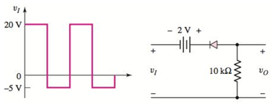
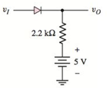
Figure P2.36
Expert Solution & Answer
Want to see the full answer?
Check out a sample textbook solution
Students have asked these similar questions
Shown below is a diode circuit. If the input signal Vs = 34 Vp-p and the DC voltage Vdc = 5 V, what is the
output voltage (in volts) of the circuit during the positive alteration of the input signal? No need to show your
solution. Just write your numeric answer on the space provided. Round off your answer to 2 decimal places.
1.0kn
...
Vdc
Vs
Vo
Si D1
Consider the following circuit with Vs(t) = 2.0+ 0.02 sin(2100t) V,
R₁ = R₂= 25 2, Idc = 1mA, Vdc = 5V. Assume Vy= 0.7V and VT = 25mV.
a) Draw the equivalent circuit under DC
b) Determine the DC voltage and current through the diode.
c) Draw the equivalent circuit under ac
d) Determine the total current through the diode
Vs
R1
W
R2
ww
C
CUP
#
Idc
D1
-Vdc
SOLVE STEP BY STEP IN DIGITAL FORMAT
For each of the circuits shown below, draw its voltage transfer curve, using the
constant-drop model (all diodes are silicon identical, V_Don = 0.7V). Consider a
variation of the input voltage from -10V to +10V.
Vi
V₁
D₁
D₁
Z
D₂
1k
Circuit 1
1k
Circuit 2
V₂
+
V₂
Vi
Vi
1k
1k
D₁
Circuit 3
D₁
1k
ww
1k
Circuit 4
+
V₂
+
V₂
Chapter 2 Solutions
Microelectronics: Circuit Analysis and Design
Ch. 2 - Repeat Example 2.1 if the input voltage is...Ch. 2 - Consider the bridge circuit shown in Figure 2.6(a)...Ch. 2 - Assume the input signal to a rectifier circuit has...Ch. 2 - The input voltage to the halfwave rectifier in...Ch. 2 - Consider the circuit in Figure 2.4. The input...Ch. 2 - The circuit in Figure 2.5(a) is used to rectify a...Ch. 2 - The secondary transformer voltage of the rectifier...Ch. 2 - Determine the fraction (percent) of the cycle that...Ch. 2 - The Zener diode regulator circuit shown in Figure...Ch. 2 - Repeat Example 2.6 for rz=4 . Assume all other...
Ch. 2 - Consider the circuit shown in Figure 2.19. Let...Ch. 2 - Suppose the currentlimiting resistor in Example...Ch. 2 - Suppose the power supply voltage in the circuit...Ch. 2 - Design a parallelbased clipper that will yield the...Ch. 2 - Sketch the steadystate output voltage for the...Ch. 2 - Consider the circuit in Figure 2.23(a). Let R1=5k...Ch. 2 - Determine the steadystate output voltage O for the...Ch. 2 - Design a parallelbased clipper circuit that will...Ch. 2 - Consider the circuit shown in Figure 2.38, in...Ch. 2 - Consider the circuit shown in Figure 2.39. The...Ch. 2 - Repeat Example 2.11 for the case when R1=8k ,...Ch. 2 - The cutin voltage of each diode in the circuit...Ch. 2 - Prob. 2.12TYUCh. 2 - Consider the OR logic circuit shown in Figure...Ch. 2 - Consider the AND logic circuit shown in Figure...Ch. 2 - (a) Photons with an energy of hv=2eV are incident...Ch. 2 - Determine the value of resistance R required to...Ch. 2 - What characteristic of a diode is used in the...Ch. 2 - Prob. 2RQCh. 2 - Describe a simple fullwave diode rectifier circuit...Ch. 2 - Prob. 4RQCh. 2 - Prob. 5RQCh. 2 - Describe a simple Zener diode voltage reference...Ch. 2 - What effect does the Zener diode resistance have...Ch. 2 - What are the general characteristics of diode...Ch. 2 - Describe a simple diode clipper circuit that...Ch. 2 - Prob. 10RQCh. 2 - What one circuit element, besides a diode, is...Ch. 2 - Prob. 12RQCh. 2 - Describe a diode OR logic circuit. Compare a logic...Ch. 2 - Describe a diode AND logic circuit. Compare a...Ch. 2 - Describe a simple circuit that can be used to turn...Ch. 2 - Consider the circuit shown in Figure P2.1. Let...Ch. 2 - For the circuit shown in Figure P2.1, show that...Ch. 2 - A halfwave rectifier such as shown in Figure...Ch. 2 - Consider the battery charging circuit shown in...Ch. 2 - Figure P2.5 shows a simple fullwave battery...Ch. 2 - The fullwave rectifier circuit shown in Figure...Ch. 2 - The input signal voltage to the fullwave rectifier...Ch. 2 - The output resistance of the fullwave rectifier in...Ch. 2 - Repeat Problem 2.8 for the halfwave rectifier in...Ch. 2 - Consider the halfwave rectifier circuit shown in...Ch. 2 - The parameters of the halfwave rectifier circuit...Ch. 2 - The fullwave rectifier circuit shown in Figure...Ch. 2 - Consider the fullwave rectifier circuit in Figure...Ch. 2 - The circuit in Figure P2.14 is a complementary...Ch. 2 - Prob. 2.15PCh. 2 - A fullwave rectifier is to be designed using the...Ch. 2 - Prob. 2.17PCh. 2 - (a) Sketch o versus time for the circuit in Figure...Ch. 2 - Consider the circuit shown in Figure P2.19. The...Ch. 2 - Consider the Zener diode circuit shown in Figure...Ch. 2 - Consider the Zener diode circuit shown in Figure...Ch. 2 - In the voltage regulator circuit in Figure P2.21,...Ch. 2 - A Zener diode is connected in a voltage regulator...Ch. 2 - Consider the Zener diode circuit in Figure 2.19 in...Ch. 2 - Design a voltage regulator circuit such as shown...Ch. 2 - The percent regulation of the Zener diode...Ch. 2 - A voltage regulator is to have a nominal output...Ch. 2 - Consider the circuit in Figure P2.28. Let V=0 ....Ch. 2 - The secondary voltage in the circuit in Figure...Ch. 2 - The parameters in the circuit shown in Figure...Ch. 2 - Consider the circuit in Figure P2.31. Let V=0 (a)...Ch. 2 - Prob. 2.32PCh. 2 - Each diode cutin voltage is 0.7 V for the circuits...Ch. 2 - The diode in the circuit of Figure P2.34(a) has...Ch. 2 - Consider the circuits shown in Figure P2.35. Each...Ch. 2 - Plot O for each circuit in Figure P2.36 for the...Ch. 2 - Consider the parallel clipper circuit in Figure...Ch. 2 - A car’s radio may be subjected to voltage spikes...Ch. 2 - Sketch the steadystate output voltage O versus...Ch. 2 - Prob. D2.40PCh. 2 - Design a diode clamper to generate a steadystate...Ch. 2 - For the circuit in Figure P2.39(b), let V=0 and...Ch. 2 - Repeat Problem 2.42 for the circuit in Figure...Ch. 2 - The diodes in the circuit in Figure P2.44 have...Ch. 2 - In the circuit in Figure P2.45 the diodes have the...Ch. 2 - The diodes in the circuit in Figure P2.46 have the...Ch. 2 - Consider the circuit shown in Figure P2.47. Assume...Ch. 2 - The diode cutin voltage for each diode in the...Ch. 2 - Consider the circuit in Figure P2.49. Each diode...Ch. 2 - Assume V=0.7V for each diode in the circuit in...Ch. 2 - The cutin voltage of each diode in the circuit...Ch. 2 - Let V=0.7V for each diode in the circuit in Figure...Ch. 2 - For the circuit shown in Figure P2.54, let V=0.7V...Ch. 2 - Assume each diode cutin voltage is V=0.7V for the...Ch. 2 - If V=0.7V for the diode in the circuit in Figure...Ch. 2 - Let V=0.7V for the diode in the circuit in Figure...Ch. 2 - Each diode cutin voltage in the circuit in Figure...Ch. 2 - Let V=0.7V for each diode in the circuit shown in...Ch. 2 - Consider the circuit in Figure P2.61. The output...Ch. 2 - Consider the circuit in Figure P2.62. The output...Ch. 2 - Prob. 2.63PCh. 2 - Consider the circuit shown in Figure P2.64. The...Ch. 2 - The lightemitting diode in the circuit shown in...Ch. 2 - The parameters of D1 and D2 in the circuit shown...Ch. 2 - If the resistor in Example 2.12 is R=2 and the...Ch. 2 - Consider the photodiode circuit shown in Figure...Ch. 2 - Consider the fullwave bridge rectifier circuit....Ch. 2 - Design a simple dc voltage source using a...Ch. 2 - A clipper is to be designed such that O=2.5V for...Ch. 2 - Design a circuit to provide the voltage transfer...
Knowledge Booster


Learn more about
Need a deep-dive on the concept behind this application? Look no further. Learn more about this topic, electrical-engineering and related others by exploring similar questions and additional content below.Similar questions
- Figure Q2(a) shows a clipper circuit made with an ideal diode. Vi(t) R 10 V• t Vi(t) Vo(t) V = 5V -10 V - Figure Q2(a) (i) Determine the output voltage for all input voltages values. (ii) Sketch the overall output waveform, Vo(t).arrow_forward1) It can be accepted that D1 and D2 diodes are from the same family in the circuit given in the figure. a) output voltage, wwwiwwwww wwwww wwwwwwwwwwn w www w 0.33 k2 wwwwww wwwww E 10 V D Si D, Si b) the current flowing through the resistor, ww ww c) currents flowing through the diodes గ wl ww ww calculate. www ww +arrow_forwardQ2 (a) Figure Q2(a) shows a clipper circuit made with a gemanium diode. Given the voltage input, Vin = 20 Vp-p, VDc = 5 V, Rs = 10N and RL=1 kN. (i) Sketch the full cycle of input voltage, Vin(t) in sinusoidal waveform. (ii) Determine the output voltage values for all input values. Show all the calculations and support your answers with the aid of diagram. R. Vin Si Ge R VOUT Vpc Figure Q2(a)arrow_forward
- In the figure given we have u(t)=10- cosot [V]. We assume the diodes and the A-meter (A) to be ideal. a) Plot the waveform of the current flowing through the A-m in scale. b) What is the reading of the A-m, if it is moving-coil type? A u(t) R1 R2 c) What is the reading of the A-m, if it is moving-iron type? d) Calculate the power factor of the WHOLE structure. 5Ω 10Ωarrow_forwardFor the given circuit below, it operates on a peak- to-peak input voltage of 112.3 V, F = 60 Hz household supply through a step-down transformer with turns N1 = 10 and N2 = 1. Silicon diodes are used with a 1 Kiloohms load. Determine the output peak voltage (in volts). D1 D2 AC Input Vsec (source) D3 .... D4 Load 4.21 4.01 7.86 7.02 elllearrow_forwardIn the given circuit, (diodes will be considered ideal. a) Draw the V0 output by calculating it according to the input. b) Calculate the average and effective value of the V0 output. c) What are the advantages and disadvantages of using two diodes and two resistors instead of four diodes? Input signal Vm = ± 10V (peak to peak), T = 2π (period), R = 2karrow_forward
- 1) Diode half-wave rectifier a) Consider the half-wave rectified sinewave voltage waveform at the right. What is the DC voltage and RMS voltage in terms of Vpeak? Remember: Vp peak ann T/2 1 Vay = DC = v(0)de avg T Sv(t)dt and V = Hve v² (t)dt Tarrow_forwardIn the given circuit, (diodes will be considered ideal.a) Draw the V0 output by calculating it according to the input.b) Calculate the average and effective value of the V0 output.c) What are the advantages and disadvantages of using two diodes and two resistors instead of four diodes?Input signal Vm = ± 10V (peak to peak), T = 2π (period), R = 32karrow_forwardQ2) Find the Performance Parameters of a Full-Wave Rectifier with an RL Load, the single-phase full-wave rectifier of the figure below has L = 6.5 mH, R = 2.52 and E= 10 V. The input voltage is Vs = 120 V at 60 Hz. Assume that the load current is continuous current. Where: V io (t) = -(sin(wt - 0)+ im Z 2 -R 1-ewr -sin 8.e *) E R Determine: (1) The steady-state load current lo at wt = 0, (2) The average diode current Ip(av), (3) The rms diode current Ip(ms), (4) The rms output current lo(ms), and (5) The input power factor PF D₁ D₂ A Pa D₂ A + Vo 1. Earrow_forward
- A designer proposes a circuit that consists of a voltage regulator (sinusoidal) input signal, vin with a peak voltage of +20 V, as shown in Figure Q3(d). As an engineer in the same department, you are required to find the solution for the maximum and minimum peak of the output signal, vour when the diode is forward and reverse bias. Ideal y Vin ER Vout 5 VE Figure Q3(d)arrow_forwardA clamper circuit has 20 Vp-p. 100Hz square wave input voltage. The circuit consists of silicon diode IN4001 and 3V battery as shown in Figure 1 C. 0.1 µF D R Vi(t) 50 k2 Vo(t) 3 V Figure 1 a) Find the output voltage for all input voltages values. b) Sketch the output waveform, Vo(t).arrow_forwardVi (t) = 10.sinwt Does not pass positive alternans when Volt input voltage is applied, only Design and explain two different circuits that pass negative alternans. Draw the input and output voltages. What are the types of these circuits? (Note: You can use the ideal diode approach)arrow_forward
arrow_back_ios
SEE MORE QUESTIONS
arrow_forward_ios
Recommended textbooks for you
 Introductory Circuit Analysis (13th Edition)Electrical EngineeringISBN:9780133923605Author:Robert L. BoylestadPublisher:PEARSON
 Delmar's Standard Textbook Of ElectricityElectrical EngineeringISBN:9781337900348Author:Stephen L. HermanPublisher:Cengage Learning
 Programmable Logic ControllersElectrical EngineeringISBN:9780073373843Author:Frank D. PetruzellaPublisher:McGraw-Hill Education
 Fundamentals of Electric CircuitsElectrical EngineeringISBN:9780078028229Author:Charles K Alexander, Matthew SadikuPublisher:McGraw-Hill Education
 Electric Circuits. (11th Edition)Electrical EngineeringISBN:9780134746968Author:James W. Nilsson, Susan RiedelPublisher:PEARSON
 Engineering ElectromagneticsElectrical EngineeringISBN:9780078028151Author:Hayt, William H. (william Hart), Jr, BUCK, John A.Publisher:Mcgraw-hill Education,
Introductory Circuit Analysis (13th Edition)
Electrical Engineering
ISBN:9780133923605
Author:Robert L. Boylestad
Publisher:PEARSON
Delmar's Standard Textbook Of Electricity
Electrical Engineering
ISBN:9781337900348
Author:Stephen L. Herman
Publisher:Cengage Learning
Programmable Logic Controllers
Electrical Engineering
ISBN:9780073373843
Author:Frank D. Petruzella
Publisher:McGraw-Hill Education
Fundamentals of Electric Circuits
Electrical Engineering
ISBN:9780078028229
Author:Charles K Alexander, Matthew Sadiku
Publisher:McGraw-Hill Education
Electric Circuits. (11th Edition)
Electrical Engineering
ISBN:9780134746968
Author:James W. Nilsson, Susan Riedel
Publisher:PEARSON
Engineering Electromagnetics
Electrical Engineering
ISBN:9780078028151
Author:Hayt, William H. (william Hart), Jr, BUCK, John A.
Publisher:Mcgraw-hill Education,
How does an Alternator Work ?; Author: Lesics;https://www.youtube.com/watch?v=tiKH48EMgKE;License: Standard Youtube License