
Microelectronics: Circuit Analysis and Design
4th Edition
ISBN: 9780073380643
Author: Donald A. Neamen
Publisher: McGraw-Hill Companies, The
expand_more
expand_more
format_list_bulleted
Concept explainers
Videos
Textbook Question
Chapter 2, Problem D2.41P
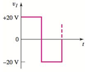
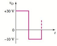
Design a diode clamper to generate a steady−state output voltage
Expert Solution & Answer
Want to see the full answer?
Check out a sample textbook solution
Students have asked these similar questions
Figure Q2(a) shows the characteristic curve of a Zener diode. Analyse the characteristic
curve to identify the approximate minimum Zener current Izk(min) and the approximate Zener
voltage, Vz at IZK.
-10 -9 -8 -7 -6 -5
-2 -1
Vz (V) +
1
3
4
6
7
8
Iz (mA)
Figure Q2(a)
Analyse the circuit in Figure Q2(b) to identify the minimum input voltage required to keep the
diode in Zener region based on the values of the minimum Zener current and the
approximated Zener voltage found in Question 2(a).
R
1k2
VIN
Figure Q2(b)
0:- Consider the circuit in Figure
a) What type of circuit is this?
b) Find and Sketch the voltage
waveform across RL, assume
the diodes are practical.
c) If 100uf
capacitor
parallel with the
resistor, calculate the ripple
is
connected
factor
I O o D
In the circuit given in the figure, find the current passing through the diode in mA since R1 = 4.95Kohm, R2 = 2.50Kohm, R3 = 1.69Kohm, R4 = 5.44Kohm, VCC = 13.00V and the diode is silicon?
Chapter 2 Solutions
Microelectronics: Circuit Analysis and Design
Ch. 2 - Repeat Example 2.1 if the input voltage is...Ch. 2 - Consider the bridge circuit shown in Figure 2.6(a)...Ch. 2 - Assume the input signal to a rectifier circuit has...Ch. 2 - The input voltage to the halfwave rectifier in...Ch. 2 - Consider the circuit in Figure 2.4. The input...Ch. 2 - The circuit in Figure 2.5(a) is used to rectify a...Ch. 2 - The secondary transformer voltage of the rectifier...Ch. 2 - Determine the fraction (percent) of the cycle that...Ch. 2 - The Zener diode regulator circuit shown in Figure...Ch. 2 - Repeat Example 2.6 for rz=4 . Assume all other...
Ch. 2 - Consider the circuit shown in Figure 2.19. Let...Ch. 2 - Suppose the currentlimiting resistor in Example...Ch. 2 - Suppose the power supply voltage in the circuit...Ch. 2 - Design a parallelbased clipper that will yield the...Ch. 2 - Sketch the steadystate output voltage for the...Ch. 2 - Consider the circuit in Figure 2.23(a). Let R1=5k...Ch. 2 - Determine the steadystate output voltage O for the...Ch. 2 - Design a parallelbased clipper circuit that will...Ch. 2 - Consider the circuit shown in Figure 2.38, in...Ch. 2 - Consider the circuit shown in Figure 2.39. The...Ch. 2 - Repeat Example 2.11 for the case when R1=8k ,...Ch. 2 - The cutin voltage of each diode in the circuit...Ch. 2 - Prob. 2.12TYUCh. 2 - Consider the OR logic circuit shown in Figure...Ch. 2 - Consider the AND logic circuit shown in Figure...Ch. 2 - (a) Photons with an energy of hv=2eV are incident...Ch. 2 - Determine the value of resistance R required to...Ch. 2 - What characteristic of a diode is used in the...Ch. 2 - Prob. 2RQCh. 2 - Describe a simple fullwave diode rectifier circuit...Ch. 2 - Prob. 4RQCh. 2 - Prob. 5RQCh. 2 - Describe a simple Zener diode voltage reference...Ch. 2 - What effect does the Zener diode resistance have...Ch. 2 - What are the general characteristics of diode...Ch. 2 - Describe a simple diode clipper circuit that...Ch. 2 - Prob. 10RQCh. 2 - What one circuit element, besides a diode, is...Ch. 2 - Prob. 12RQCh. 2 - Describe a diode OR logic circuit. Compare a logic...Ch. 2 - Describe a diode AND logic circuit. Compare a...Ch. 2 - Describe a simple circuit that can be used to turn...Ch. 2 - Consider the circuit shown in Figure P2.1. Let...Ch. 2 - For the circuit shown in Figure P2.1, show that...Ch. 2 - A halfwave rectifier such as shown in Figure...Ch. 2 - Consider the battery charging circuit shown in...Ch. 2 - Figure P2.5 shows a simple fullwave battery...Ch. 2 - The fullwave rectifier circuit shown in Figure...Ch. 2 - The input signal voltage to the fullwave rectifier...Ch. 2 - The output resistance of the fullwave rectifier in...Ch. 2 - Repeat Problem 2.8 for the halfwave rectifier in...Ch. 2 - Consider the halfwave rectifier circuit shown in...Ch. 2 - The parameters of the halfwave rectifier circuit...Ch. 2 - The fullwave rectifier circuit shown in Figure...Ch. 2 - Consider the fullwave rectifier circuit in Figure...Ch. 2 - The circuit in Figure P2.14 is a complementary...Ch. 2 - Prob. 2.15PCh. 2 - A fullwave rectifier is to be designed using the...Ch. 2 - Prob. 2.17PCh. 2 - (a) Sketch o versus time for the circuit in Figure...Ch. 2 - Consider the circuit shown in Figure P2.19. The...Ch. 2 - Consider the Zener diode circuit shown in Figure...Ch. 2 - Consider the Zener diode circuit shown in Figure...Ch. 2 - In the voltage regulator circuit in Figure P2.21,...Ch. 2 - A Zener diode is connected in a voltage regulator...Ch. 2 - Consider the Zener diode circuit in Figure 2.19 in...Ch. 2 - Design a voltage regulator circuit such as shown...Ch. 2 - The percent regulation of the Zener diode...Ch. 2 - A voltage regulator is to have a nominal output...Ch. 2 - Consider the circuit in Figure P2.28. Let V=0 ....Ch. 2 - The secondary voltage in the circuit in Figure...Ch. 2 - The parameters in the circuit shown in Figure...Ch. 2 - Consider the circuit in Figure P2.31. Let V=0 (a)...Ch. 2 - Prob. 2.32PCh. 2 - Each diode cutin voltage is 0.7 V for the circuits...Ch. 2 - The diode in the circuit of Figure P2.34(a) has...Ch. 2 - Consider the circuits shown in Figure P2.35. Each...Ch. 2 - Plot O for each circuit in Figure P2.36 for the...Ch. 2 - Consider the parallel clipper circuit in Figure...Ch. 2 - A car’s radio may be subjected to voltage spikes...Ch. 2 - Sketch the steadystate output voltage O versus...Ch. 2 - Prob. D2.40PCh. 2 - Design a diode clamper to generate a steadystate...Ch. 2 - For the circuit in Figure P2.39(b), let V=0 and...Ch. 2 - Repeat Problem 2.42 for the circuit in Figure...Ch. 2 - The diodes in the circuit in Figure P2.44 have...Ch. 2 - In the circuit in Figure P2.45 the diodes have the...Ch. 2 - The diodes in the circuit in Figure P2.46 have the...Ch. 2 - Consider the circuit shown in Figure P2.47. Assume...Ch. 2 - The diode cutin voltage for each diode in the...Ch. 2 - Consider the circuit in Figure P2.49. Each diode...Ch. 2 - Assume V=0.7V for each diode in the circuit in...Ch. 2 - The cutin voltage of each diode in the circuit...Ch. 2 - Let V=0.7V for each diode in the circuit in Figure...Ch. 2 - For the circuit shown in Figure P2.54, let V=0.7V...Ch. 2 - Assume each diode cutin voltage is V=0.7V for the...Ch. 2 - If V=0.7V for the diode in the circuit in Figure...Ch. 2 - Let V=0.7V for the diode in the circuit in Figure...Ch. 2 - Each diode cutin voltage in the circuit in Figure...Ch. 2 - Let V=0.7V for each diode in the circuit shown in...Ch. 2 - Consider the circuit in Figure P2.61. The output...Ch. 2 - Consider the circuit in Figure P2.62. The output...Ch. 2 - Prob. 2.63PCh. 2 - Consider the circuit shown in Figure P2.64. The...Ch. 2 - The lightemitting diode in the circuit shown in...Ch. 2 - The parameters of D1 and D2 in the circuit shown...Ch. 2 - If the resistor in Example 2.12 is R=2 and the...Ch. 2 - Consider the photodiode circuit shown in Figure...Ch. 2 - Consider the fullwave bridge rectifier circuit....Ch. 2 - Design a simple dc voltage source using a...Ch. 2 - A clipper is to be designed such that O=2.5V for...Ch. 2 - Design a circuit to provide the voltage transfer...
Knowledge Booster


Learn more about
Need a deep-dive on the concept behind this application? Look no further. Learn more about this topic, electrical-engineering and related others by exploring similar questions and additional content below.Similar questions
- Consider a junction diode has dc biased current at operating point ID=0.8 mA. A sinusoidal voltage is superimposed on the VD such that the peak-to-peak sinusoidal current id(t) = 0.05ID. Find the value of the applied peak-to-peak sinusoidal voltage vd(t).arrow_forwardConsider a silicon pn junction diode at T 300K. The reverse saturation current is Is = 10-14 A and the ideality factor n = 1. Determine the diode current for a diode voltage of VD = 0.573 V and use that to determine the DC and AC resistance of the diode. RDC = 14.13 k rac = 639 Q RDC = 234 Q2 = rac=8Q RDC = 7.00 KQ rac = 307 Q RDC = 1.43 kQ rac = 58 Qarrow_forwardConsider the circuit in the figure below 4:1 120 V rms ooooo gll reelee D₁ L a. What type of circuit is this? b. What is the total peak secondary voltage? D₂ c. Find the peak voltage across each half of the secondary. d. Sketch the voltage waveform across RL. e. What is the peak current through each diode? f. What is the PIV for each diode? RL 1.0 ΚΩarrow_forward
- Consider a Zener diode in the figure given below where, V1 = 30 V. Determine the Zener current IZ if RZ = 100 Ω.arrow_forward3: Using silicon diode design a clamper that will produce output V,-20Sin wt+10 (v) when the input voltage is Vo=20Sin wt-10 (V).Draw the circuit diagram and the input and output signals. 4:The 6-V zener diode has a maximum rated power dissipated of 690 mw.Its reveres current must be at least 3mA to keep it in breakdown. Find a suitable value for Rs if V; can vary from 9v to 12v and Ri. can vary from 5000 to 1.2KO.arrow_forwardFor the circuit shown in Figure 2, sketch the output voltage (across the load 2.2 KN resistor) and the load current (through the load 2.2 Kn resistor). Sketch the diode voltage (across the diode D1) and the diode current (through the diode DI). The input V. is sinusoidal with maximum amplitude (peak) of 100 V and frequency of 700 Hz. The diode DI is a Silicon diode. The sketches have to be at least for two cycles of the input. D1 2.2 K2 Viarrow_forward
- The zener diode in the voltage-regulator circuit given below has a breakdown voltage of 9V. Suppose that the diode has a resistance of 1002 in the breakdown state and diode is to operate with a reverse current between 10mA and 100mA. Find the range of VS for the case that R = 2002 and RL = 6002. Is IL R + レ RL VL VS + +arrow_forwardconsider the figure below that shows an approximated reverse recovery turn-off characteristics for a power diode. Show that the following relation can express the total reverse recovery charge, Qrr = 1/2(trr*ts1) di1/dt =1/2(trr*ts21) di2/dt * ip Isl 1s2! -Irarrow_forwardSince R1=4.51 Kohm, R2=1.19 Kohm R3=2.74Kohm R4=5.60Kohm VCC=23.00V and diode silicon in the circuit given in the figure, find the current passing through the diode in mAarrow_forward
- Determine the negative resistance for the tunnel diode in the figure between ?T = 0.2 ? and ?T = 0.4arrow_forwardThe zener diode in the voltage-regulator circuit given below has a breakdown voltage of 9V. Suppose that the diode has a resistance of 1002 in the breakdown state and diode is to operate with a reverse current between 10mA and 100mA. Find the range of VS for the case that R = 2002 and RL = 6002. Is IL R VS V RL VL + > + + +arrow_forwarduO 9:.0 A docs.google.com * ZAIN IQ l. Q3/B: Assume an ideal diode model for all the diodes in the circuit below. calculate voltages and currents through D1 and D2 9kQ 1N1199C R2 D1 18KQ 1N1199C D3 1N1199C V2 =12 V R3 1kQ R4 5kQ 1.22 V 11 mA 0.5 A O VD1 ID1 VD2 ID2 صفحة 4 من 6arrow_forward
arrow_back_ios
SEE MORE QUESTIONS
arrow_forward_ios
Recommended textbooks for you
 Introductory Circuit Analysis (13th Edition)Electrical EngineeringISBN:9780133923605Author:Robert L. BoylestadPublisher:PEARSON
 Delmar's Standard Textbook Of ElectricityElectrical EngineeringISBN:9781337900348Author:Stephen L. HermanPublisher:Cengage Learning
 Programmable Logic ControllersElectrical EngineeringISBN:9780073373843Author:Frank D. PetruzellaPublisher:McGraw-Hill Education
 Fundamentals of Electric CircuitsElectrical EngineeringISBN:9780078028229Author:Charles K Alexander, Matthew SadikuPublisher:McGraw-Hill Education
 Electric Circuits. (11th Edition)Electrical EngineeringISBN:9780134746968Author:James W. Nilsson, Susan RiedelPublisher:PEARSON
 Engineering ElectromagneticsElectrical EngineeringISBN:9780078028151Author:Hayt, William H. (william Hart), Jr, BUCK, John A.Publisher:Mcgraw-hill Education,
Introductory Circuit Analysis (13th Edition)
Electrical Engineering
ISBN:9780133923605
Author:Robert L. Boylestad
Publisher:PEARSON
Delmar's Standard Textbook Of Electricity
Electrical Engineering
ISBN:9781337900348
Author:Stephen L. Herman
Publisher:Cengage Learning
Programmable Logic Controllers
Electrical Engineering
ISBN:9780073373843
Author:Frank D. Petruzella
Publisher:McGraw-Hill Education
Fundamentals of Electric Circuits
Electrical Engineering
ISBN:9780078028229
Author:Charles K Alexander, Matthew Sadiku
Publisher:McGraw-Hill Education
Electric Circuits. (11th Edition)
Electrical Engineering
ISBN:9780134746968
Author:James W. Nilsson, Susan Riedel
Publisher:PEARSON
Engineering Electromagnetics
Electrical Engineering
ISBN:9780078028151
Author:Hayt, William H. (william Hart), Jr, BUCK, John A.
Publisher:Mcgraw-hill Education,
Diodes Explained - The basics how diodes work working principle pn junction; Author: The Engineering Mindset;https://www.youtube.com/watch?v=Fwj_d3uO5g8;License: Standard Youtube License