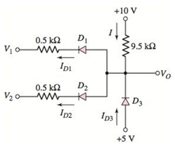
The diodes in the circuit in Figure P2.46 have the same piecewise linear parameters as described in Problem 2.44. Determine the output voltage V O and the currents I D 1 , I D 2 , I D 3 , and I for the following input conditions: (a) V 1 = V 2 = 0 ; (b) V 1 = V 2 = 5 V ; (c) V 1 = 5 V , V 2 = 0 ; and (d) V 1 = 5 V , V 2 = 2 V . Figure P2.46
The diodes in the circuit in Figure P2.46 have the same piecewise linear parameters as described in Problem 2.44. Determine the output voltage V O and the currents I D 1 , I D 2 , I D 3 , and I for the following input conditions: (a) V 1 = V 2 = 0 ; (b) V 1 = V 2 = 5 V ; (c) V 1 = 5 V , V 2 = 0 ; and (d) V 1 = 5 V , V 2 = 2 V . Figure P2.46
Solution Summary: The author explains the output voltage and diode currents of the given circuit.
The diodes in the circuit in Figure P2.46 have the same piecewise linear parameters as described in Problem 2.44. Determine the output voltage
V
O
and the currents
I
D
1
,
I
D
2
,
I
D
3
, and I for the following input conditions: (a)
V
1
=
V
2
=
0
; (b)
V
1
=
V
2
=
5
V
; (c)
V
1
=
5
V
,
V
2
=
0
; and (d)
V
1
=
5
V
,
V
2
=
2
V
.
2. (35 points) Use you program to investigative properties of a four step linear pathway. Just
extend the model given in question 1 to include an additional two species x2 and x3. You can
assume simple irreversible mass-action kinetic on each reaction.
I recommend you use the following values for the rate constants: 1 = 0.6; k2 = 1.8; k3 =
0.5; k40.04. This will enable you to more easily answer the following questions.
You can also assume that the input is the source X and you can set its value to one.
You may find that the plot of the phase change at x3 is broken at -180 degrees because it wraps
around. To avoid this you can use the method:
phase = np.unwrap(phase)
to make sure the phase plot is continuous.
[10] i) Compute and show the Bode plots for x1, x2 and x3 with respect to the input Xo.
[5] ii) Do you see a pattern with the maximum phase shifts as you move from x₁ to x3?
[10] iii) Can you explain this pattern?
[5] iv) What would you predict would be the maximum phase shift for…
Please answer all
The zombies showed up while you were sleeping! The zombie alarm you built goes off as they open the door. You jolt awake to see an alpha-zombie charging through the door. The alphas are zombies that turned all of the zombies in its army. If you can take down this one zombie, all the others pouring into the room should fall as well. Luckily, your group was prepared for this eventuality. Another member of your team has constructed the zombie shocker circuit shown in Figure 5, using some batteries for the voltage source, some rusty metal for the resistors and a coil of wire for the inductor. The switch is just you pulling apart two wires to open the circuit (while holding them by their insulated sheaths).
1. Construct the circuit shown in Figure 15 in the Circuit JS simulator. 2. Start the simulation with switch SW1 in the closed position. You’ve been charging this circuit all night, so you’ll want to let the circuit run for a while (roughly 30 seconds at max…
Please answer all questions
1. Calculate the values of the following without using Circuit JS. Assume the circuit has reached steady state. Show these calculations: a) Voltage across and current through C1. b) Voltage across and current through L1. c) Voltage across and current through R5. 2. Construct the circuit in the Circuit JS simulator [1]. 3. Perform a simulation and determine the following values. Record them. Allow the circuit to reach steady state. a) Voltage across and current through C1. b) Voltage across and current through L1. c) Voltage across and current through R5. 4. Include a screen shot of the simulator window (including showing the values listed above). 5. Answer the following questions: a) In a DC circuit, what does a capacitor look like?
b) In a DC circuit, what does an inductor look like?
Need a deep-dive on the concept behind this application? Look no further. Learn more about this topic, electrical-engineering and related others by exploring similar questions and additional content below.
What is an electric furnace and how does it work?; Author: Fire & Ice Heating and Air Conditioning Inc;https://www.youtube.com/watch?v=wjAWecPGi0M;License: Standard Youtube License


 Introductory Circuit Analysis (13th Edition)Electrical EngineeringISBN:9780133923605Author:Robert L. BoylestadPublisher:PEARSON
 Delmar's Standard Textbook Of ElectricityElectrical EngineeringISBN:9781337900348Author:Stephen L. HermanPublisher:Cengage Learning
 Programmable Logic ControllersElectrical EngineeringISBN:9780073373843Author:Frank D. PetruzellaPublisher:McGraw-Hill Education
 Fundamentals of Electric CircuitsElectrical EngineeringISBN:9780078028229Author:Charles K Alexander, Matthew SadikuPublisher:McGraw-Hill Education
 Electric Circuits. (11th Edition)Electrical EngineeringISBN:9780134746968Author:James W. Nilsson, Susan RiedelPublisher:PEARSON
 Engineering ElectromagneticsElectrical EngineeringISBN:9780078028151Author:Hayt, William H. (william Hart), Jr, BUCK, John A.Publisher:Mcgraw-hill Education,