
Microelectronics: Circuit Analysis and Design
4th Edition
ISBN: 9780073380643
Author: Donald A. Neamen
Publisher: McGraw-Hill Companies, The
expand_more
expand_more
format_list_bulleted
Videos
Textbook Question
Chapter 2, Problem 2.8EP
Sketch the steady−state output voltage for the input signal given for the circuit shown in Figure 2.30. Assume
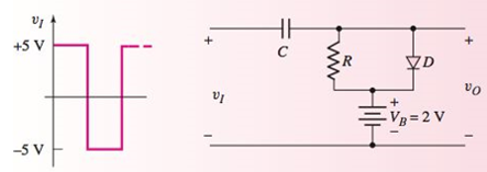
Figure 2.30 Figure for Exercise Ex 2.8
Expert Solution & Answer
Want to see the full answer?
Check out a sample textbook solution
Students have asked these similar questions
e average voltage of Vo.
5 URM U
2 Figure B.2 shows a circuit using two silicon diodes with knee voltage of 0.7 V. The
supply voltage, Vs, is a sinusoidal AC signal. The produced output, Vo, is a
fluctuating DC signal with ripple peak-to-peak voltage of I.58 V.
& UTM UTM
UTM STM
DI
5 UTM O UTM
50 Hz
&UTM UTM UTM
5 UTM UTM UTM
50 µF
RL
UTM & UTM
D2
&UTM/ UTMTUTM
(a) Determine the
SITM
(b) Determine the peak voltage of the Vs.
5 UTM
(c) Consider
UTM &UTM & UTM
waveform of Vo with complete labelling.
en Ci is removed from the circuit (i.e. open circuit). Draw the
5 UTM & UTM
UTM U1 A
TM 5 UTM UTM
TM 5 UTM UTM
S-4) The input signal Vin of the clipper circuit given below is a sinusoidal signal of Vp-p = 30V and the wave the form is as given in the figure.
a) Plot the output waveform of this circuit in the area given for + and - alternans.
b) Calculate the peak values of the output and indicate it on the graph. Note: Diode threshold voltage will be 0.7V
The Figure 2 shows an electronic circuit designed for supplying power to a load (R1). The
supply voltage 235V (RMS, AC) at frequency of 50HZ. The required DC voltage and power
for the load are 24V and 3.6 W respectively.
The Electrical Components of this AC to DC converter are:
A full-wave rectifier to convert AC voltage to DC voltage.
A regulator with transistor and Zener diode to ensure a constant voltage and power
for the load.
D1
Iide
91
Vaut
VLoad
D2 D3
Vde
VI
sine
R1
RL
Regulate
Reetifier
Figure 2. Complete Circuit
Assume that the diodes are real diodes (NOT ideal diodes). The following information is
available:
The collector to base resistor of the regulator R1 = 5.0 k
The transistor Q1 with B value of 24 is used for the regulator circuit.
Determine the following quantities for this electronic device and fill the table below:
Question
Answer
The voltage of Zener Diode (Vz)
The current in R1
The DC current into the regulator
| (Idc)
Base current of transistor (IB)
Collector…
Chapter 2 Solutions
Microelectronics: Circuit Analysis and Design
Ch. 2 - Repeat Example 2.1 if the input voltage is...Ch. 2 - Consider the bridge circuit shown in Figure 2.6(a)...Ch. 2 - Assume the input signal to a rectifier circuit has...Ch. 2 - The input voltage to the halfwave rectifier in...Ch. 2 - Consider the circuit in Figure 2.4. The input...Ch. 2 - The circuit in Figure 2.5(a) is used to rectify a...Ch. 2 - The secondary transformer voltage of the rectifier...Ch. 2 - Determine the fraction (percent) of the cycle that...Ch. 2 - The Zener diode regulator circuit shown in Figure...Ch. 2 - Repeat Example 2.6 for rz=4 . Assume all other...
Ch. 2 - Consider the circuit shown in Figure 2.19. Let...Ch. 2 - Suppose the currentlimiting resistor in Example...Ch. 2 - Suppose the power supply voltage in the circuit...Ch. 2 - Design a parallelbased clipper that will yield the...Ch. 2 - Sketch the steadystate output voltage for the...Ch. 2 - Consider the circuit in Figure 2.23(a). Let R1=5k...Ch. 2 - Determine the steadystate output voltage O for the...Ch. 2 - Design a parallelbased clipper circuit that will...Ch. 2 - Consider the circuit shown in Figure 2.38, in...Ch. 2 - Consider the circuit shown in Figure 2.39. The...Ch. 2 - Repeat Example 2.11 for the case when R1=8k ,...Ch. 2 - The cutin voltage of each diode in the circuit...Ch. 2 - Prob. 2.12TYUCh. 2 - Consider the OR logic circuit shown in Figure...Ch. 2 - Consider the AND logic circuit shown in Figure...Ch. 2 - (a) Photons with an energy of hv=2eV are incident...Ch. 2 - Determine the value of resistance R required to...Ch. 2 - What characteristic of a diode is used in the...Ch. 2 - Prob. 2RQCh. 2 - Describe a simple fullwave diode rectifier circuit...Ch. 2 - Prob. 4RQCh. 2 - Prob. 5RQCh. 2 - Describe a simple Zener diode voltage reference...Ch. 2 - What effect does the Zener diode resistance have...Ch. 2 - What are the general characteristics of diode...Ch. 2 - Describe a simple diode clipper circuit that...Ch. 2 - Prob. 10RQCh. 2 - What one circuit element, besides a diode, is...Ch. 2 - Prob. 12RQCh. 2 - Describe a diode OR logic circuit. Compare a logic...Ch. 2 - Describe a diode AND logic circuit. Compare a...Ch. 2 - Describe a simple circuit that can be used to turn...Ch. 2 - Consider the circuit shown in Figure P2.1. Let...Ch. 2 - For the circuit shown in Figure P2.1, show that...Ch. 2 - A halfwave rectifier such as shown in Figure...Ch. 2 - Consider the battery charging circuit shown in...Ch. 2 - Figure P2.5 shows a simple fullwave battery...Ch. 2 - The fullwave rectifier circuit shown in Figure...Ch. 2 - The input signal voltage to the fullwave rectifier...Ch. 2 - The output resistance of the fullwave rectifier in...Ch. 2 - Repeat Problem 2.8 for the halfwave rectifier in...Ch. 2 - Consider the halfwave rectifier circuit shown in...Ch. 2 - The parameters of the halfwave rectifier circuit...Ch. 2 - The fullwave rectifier circuit shown in Figure...Ch. 2 - Consider the fullwave rectifier circuit in Figure...Ch. 2 - The circuit in Figure P2.14 is a complementary...Ch. 2 - Prob. 2.15PCh. 2 - A fullwave rectifier is to be designed using the...Ch. 2 - Prob. 2.17PCh. 2 - (a) Sketch o versus time for the circuit in Figure...Ch. 2 - Consider the circuit shown in Figure P2.19. The...Ch. 2 - Consider the Zener diode circuit shown in Figure...Ch. 2 - Consider the Zener diode circuit shown in Figure...Ch. 2 - In the voltage regulator circuit in Figure P2.21,...Ch. 2 - A Zener diode is connected in a voltage regulator...Ch. 2 - Consider the Zener diode circuit in Figure 2.19 in...Ch. 2 - Design a voltage regulator circuit such as shown...Ch. 2 - The percent regulation of the Zener diode...Ch. 2 - A voltage regulator is to have a nominal output...Ch. 2 - Consider the circuit in Figure P2.28. Let V=0 ....Ch. 2 - The secondary voltage in the circuit in Figure...Ch. 2 - The parameters in the circuit shown in Figure...Ch. 2 - Consider the circuit in Figure P2.31. Let V=0 (a)...Ch. 2 - Prob. 2.32PCh. 2 - Each diode cutin voltage is 0.7 V for the circuits...Ch. 2 - The diode in the circuit of Figure P2.34(a) has...Ch. 2 - Consider the circuits shown in Figure P2.35. Each...Ch. 2 - Plot O for each circuit in Figure P2.36 for the...Ch. 2 - Consider the parallel clipper circuit in Figure...Ch. 2 - A car’s radio may be subjected to voltage spikes...Ch. 2 - Sketch the steadystate output voltage O versus...Ch. 2 - Prob. D2.40PCh. 2 - Design a diode clamper to generate a steadystate...Ch. 2 - For the circuit in Figure P2.39(b), let V=0 and...Ch. 2 - Repeat Problem 2.42 for the circuit in Figure...Ch. 2 - The diodes in the circuit in Figure P2.44 have...Ch. 2 - In the circuit in Figure P2.45 the diodes have the...Ch. 2 - The diodes in the circuit in Figure P2.46 have the...Ch. 2 - Consider the circuit shown in Figure P2.47. Assume...Ch. 2 - The diode cutin voltage for each diode in the...Ch. 2 - Consider the circuit in Figure P2.49. Each diode...Ch. 2 - Assume V=0.7V for each diode in the circuit in...Ch. 2 - The cutin voltage of each diode in the circuit...Ch. 2 - Let V=0.7V for each diode in the circuit in Figure...Ch. 2 - For the circuit shown in Figure P2.54, let V=0.7V...Ch. 2 - Assume each diode cutin voltage is V=0.7V for the...Ch. 2 - If V=0.7V for the diode in the circuit in Figure...Ch. 2 - Let V=0.7V for the diode in the circuit in Figure...Ch. 2 - Each diode cutin voltage in the circuit in Figure...Ch. 2 - Let V=0.7V for each diode in the circuit shown in...Ch. 2 - Consider the circuit in Figure P2.61. The output...Ch. 2 - Consider the circuit in Figure P2.62. The output...Ch. 2 - Prob. 2.63PCh. 2 - Consider the circuit shown in Figure P2.64. The...Ch. 2 - The lightemitting diode in the circuit shown in...Ch. 2 - The parameters of D1 and D2 in the circuit shown...Ch. 2 - If the resistor in Example 2.12 is R=2 and the...Ch. 2 - Consider the photodiode circuit shown in Figure...Ch. 2 - Consider the fullwave bridge rectifier circuit....Ch. 2 - Design a simple dc voltage source using a...Ch. 2 - A clipper is to be designed such that O=2.5V for...Ch. 2 - Design a circuit to provide the voltage transfer...
Knowledge Booster


Learn more about
Need a deep-dive on the concept behind this application? Look no further. Learn more about this topic, electrical-engineering and related others by exploring similar questions and additional content below.Similar questions
- (b) Determine the peak voltage of the Vs.TM (a) Determine the average voltage of Vo. 5 URM supply voltage, Vs, is a sinusoidal AC signal. The produced output, Vo, is a fluctuating DC signal with ripple peak-to-peak voltage of 1.58 V. Figure B.2 shows a circuit using two silicon diodes with knee voltage of 0.7 V. The UTM UTM S; TM 3 UTM E UTM2:2 DI UTM UTM 50 Hz &UTM UTM 8 UTM 5 UTM TM UTM 50 μ F RL UTM UTM UTM TOTM D, &UTM TM & UTM STM (b) Determine the peak voltage of the Vs. (a) Determine the average voltage of Vo. K UTM Figure B.2 UTM (c) Consider when UTM UTM & UTM waveform of Vo with complete labelling. Ci is removed from the circuit (i.e, open circuit). Draw the FUT O UTM UTMarrow_forwardUsing a positive Clamper with positive biasing voltage Circuit, with an AC voltage of Vi = 20v with a frequency of 60hz, a value of 500n for the Capacitor, a silicon diode, biased voltage voltage of 5 volts and a resistor with the value of 300 ohms. Find the current on the resistor at a simulation of 20ms in mA. Vm 2Vm R V,m Vo -Vm V, Input Waveform Output Waveform Positive Clamper with positive reference V, wwwarrow_forwardDraw the signal after adding -2.5 DC level with the given signal, sketch the new output signal and draw the required circuit and briefly specify the function of the circuit also name this phenomenon. 10arrow_forward
- Q1. a) Figure Q1 is a single phase 2-level voltage source converter (VSC) with a total DC voltage V-1000V. A PWM scheme, by comparing a reference value with a 1kHz triangular waveform, is used to control the switches S₁ and S2, and output 340v at Vo. With the aid of graphs explain how pulse signals for the switches are generated, sketch the output voltage Vo, determine the duty cycle and the modulation index. Va + 2 it Va d + TS₁ V {1+5₂ = Figure Q1 A single phase VSCarrow_forwardFor the circuit shown in Figure 2, sketch the output voltage (across the load 2.2 KN resistor) and the load current (through the load 2.2 Kn resistor). Sketch the diode voltage (across the diode D1) and the diode current (through the diode DI). The input V. is sinusoidal with maximum amplitude (peak) of 100 V and frequency of 700 Hz. The diode DI is a Silicon diode. The sketches have to be at least for two cycles of the input. D1 2.2 K2 Viarrow_forwardA resistor Ra is in series with a voltage source Va. Draw the circuit. Label the voltage across the combination as v and the current as i. Draw and label the volt–ampere characteristic (i versus v).arrow_forward
- Consider the circuit given in Figure (Q4). Let V, = 0.8 V and R = 100 0, find: a) The value of C that results in a ripple voltage not larger than 1 V peak-to- peak. b) The DC voltage at the output c) The current through the load d) The diodes' conduction angle D, 12V (ths) 6. HZ R + Figure (Q4)arrow_forward2 V 1ΚΩ VOUT Find the following: a. Vout b. Small signal model of the diode under these conditions (Do NOT consider capacitance across the diode junction and the resistance of the semiconductor material outside the diode junction) c. Approx. peak-to-peak value of the AC component of Vout if a 1 mV RMS sinusoidal signal is added to the 2 V DC source. Given that: reverse saturation current is 1.5 x 10⁻¹⁴ A, ideality factor is 1.1, and the circuit is operating at 27°C.arrow_forward3. A step-up chopper is to provide a 48V across a 12Y~load from a 12V d.c. supply. The chopper inductance is 10tzH and the chopper frequency is 100kHz. Determine the duty cycle required and the variation of battery current during switching, and the maximum and minimum battery currentsarrow_forward
- please give detail explain.. Ans : Rth = 28 ohm Vth = 92 Varrow_forwardFor the circuit diagrams in Figure 2, name the circuits and determine the output waveform by matching a row to a column. R1 (a) (e) 4. (a) (b) (f) (c) (g) (b) (d) (h) Figure 2. Figure 3. Figure 3(a) as input to Choose... Figure 2(a) Figure 3(b) as input to Figure 2(b) Choose... Figure 3(c) as input to Figure 2(a) Choose... Figure 3(c) as input to Choose... Figure 2(b) Figure 2(b) Choose... Figure 2(a) Choose...arrow_forwardThree-phase half wave rectifier supply resistive load with DC power of 4 kW; the ammeter connected with D1 indicates 8 A r.m.s current, and the source frequency is 50 Hz Due to system inductance the average voltage drops to 96.2% of idealized value ( when the inductance is neglected). How much will the average and r.m.s voltage s be? The r.m.s phase current and average load current Is=? & Idc=? The secondary r.m.s voltage and transformer capacity Vs & KVA? The inductances causes the voltage drop Lc=? The diode forward current and maximum inverse voltage? Now, if the phase B is failed ( disconnected), how much with new dc voltage be in %..Vdc=….% ??arrow_forward
arrow_back_ios
SEE MORE QUESTIONS
arrow_forward_ios
Recommended textbooks for you
 Introductory Circuit Analysis (13th Edition)Electrical EngineeringISBN:9780133923605Author:Robert L. BoylestadPublisher:PEARSON
 Delmar's Standard Textbook Of ElectricityElectrical EngineeringISBN:9781337900348Author:Stephen L. HermanPublisher:Cengage Learning
 Programmable Logic ControllersElectrical EngineeringISBN:9780073373843Author:Frank D. PetruzellaPublisher:McGraw-Hill Education
 Fundamentals of Electric CircuitsElectrical EngineeringISBN:9780078028229Author:Charles K Alexander, Matthew SadikuPublisher:McGraw-Hill Education
 Electric Circuits. (11th Edition)Electrical EngineeringISBN:9780134746968Author:James W. Nilsson, Susan RiedelPublisher:PEARSON
 Engineering ElectromagneticsElectrical EngineeringISBN:9780078028151Author:Hayt, William H. (william Hart), Jr, BUCK, John A.Publisher:Mcgraw-hill Education,
Introductory Circuit Analysis (13th Edition)
Electrical Engineering
ISBN:9780133923605
Author:Robert L. Boylestad
Publisher:PEARSON
Delmar's Standard Textbook Of Electricity
Electrical Engineering
ISBN:9781337900348
Author:Stephen L. Herman
Publisher:Cengage Learning
Programmable Logic Controllers
Electrical Engineering
ISBN:9780073373843
Author:Frank D. Petruzella
Publisher:McGraw-Hill Education
Fundamentals of Electric Circuits
Electrical Engineering
ISBN:9780078028229
Author:Charles K Alexander, Matthew Sadiku
Publisher:McGraw-Hill Education
Electric Circuits. (11th Edition)
Electrical Engineering
ISBN:9780134746968
Author:James W. Nilsson, Susan Riedel
Publisher:PEARSON
Engineering Electromagnetics
Electrical Engineering
ISBN:9780078028151
Author:Hayt, William H. (william Hart), Jr, BUCK, John A.
Publisher:Mcgraw-hill Education,
Diode Logic Gates - OR, NOR, AND, & NAND; Author: The Organic Chemistry Tutor;https://www.youtube.com/watch?v=9lqwSaIDm2g;License: Standard Youtube License