
Microelectronics: Circuit Analysis and Design
4th Edition
ISBN: 9780073380643
Author: Donald A. Neamen
Publisher: McGraw-Hill Companies, The
expand_more
expand_more
format_list_bulleted
Videos
Textbook Question
Chapter 2, Problem 2.2P
For the circuit shown in Figure P2.1, show that for
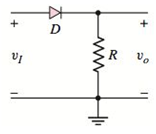
Figure P2.1
Expert Solution & Answer
Want to see the full answer?
Check out a sample textbook solution
Students have asked these similar questions
Compute the convolution y[n] = x[n] *h[n] of the following pairs of signals:
(d) x[n] and h[n] are as in Figure P2.21.
1012345
x[n]
h[n]
IIIII….…..IIIII
0 1 2 3 4 5 6 7 8 9 10 11 12 13 14 15 16
Figure P2.21
Q2: A buck converter feeding a variable resistive load is shown in the figure. The switching frequency
of the switch S is 100 kHz and the duty ratio is 0.6. The output voltage Vo is 36 V. Assume that all
the components are ideal, and that the output voltage is ripple-free. The value of R (in Ohm) that will
make the inductor current (i.) just continuous is.
5 mH
60 V +
36 V
Vo
R
Q2: A buck converter feeding a variable resistive load is shown in the figure. The switching frequency
of the switch S is 100 kHz and the duty ratio is 0.6. The output voltage Vo is 36 V. Assume that all
the components are ideal, and that the output voltage is ripple-free. The value of R (in Ohm) that will
make the inductor current (i.) just continuous is
5 mH
in
60 V +
36 V
Vo
R
Answer : 2480 to 2520
Chapter 2 Solutions
Microelectronics: Circuit Analysis and Design
Ch. 2 - Repeat Example 2.1 if the input voltage is...Ch. 2 - Consider the bridge circuit shown in Figure 2.6(a)...Ch. 2 - Assume the input signal to a rectifier circuit has...Ch. 2 - The input voltage to the halfwave rectifier in...Ch. 2 - Consider the circuit in Figure 2.4. The input...Ch. 2 - The circuit in Figure 2.5(a) is used to rectify a...Ch. 2 - The secondary transformer voltage of the rectifier...Ch. 2 - Determine the fraction (percent) of the cycle that...Ch. 2 - The Zener diode regulator circuit shown in Figure...Ch. 2 - Repeat Example 2.6 for rz=4 . Assume all other...
Ch. 2 - Consider the circuit shown in Figure 2.19. Let...Ch. 2 - Suppose the currentlimiting resistor in Example...Ch. 2 - Suppose the power supply voltage in the circuit...Ch. 2 - Design a parallelbased clipper that will yield the...Ch. 2 - Sketch the steadystate output voltage for the...Ch. 2 - Consider the circuit in Figure 2.23(a). Let R1=5k...Ch. 2 - Determine the steadystate output voltage O for the...Ch. 2 - Design a parallelbased clipper circuit that will...Ch. 2 - Consider the circuit shown in Figure 2.38, in...Ch. 2 - Consider the circuit shown in Figure 2.39. The...Ch. 2 - Repeat Example 2.11 for the case when R1=8k ,...Ch. 2 - The cutin voltage of each diode in the circuit...Ch. 2 - Prob. 2.12TYUCh. 2 - Consider the OR logic circuit shown in Figure...Ch. 2 - Consider the AND logic circuit shown in Figure...Ch. 2 - (a) Photons with an energy of hv=2eV are incident...Ch. 2 - Determine the value of resistance R required to...Ch. 2 - What characteristic of a diode is used in the...Ch. 2 - Prob. 2RQCh. 2 - Describe a simple fullwave diode rectifier circuit...Ch. 2 - Prob. 4RQCh. 2 - Prob. 5RQCh. 2 - Describe a simple Zener diode voltage reference...Ch. 2 - What effect does the Zener diode resistance have...Ch. 2 - What are the general characteristics of diode...Ch. 2 - Describe a simple diode clipper circuit that...Ch. 2 - Prob. 10RQCh. 2 - What one circuit element, besides a diode, is...Ch. 2 - Prob. 12RQCh. 2 - Describe a diode OR logic circuit. Compare a logic...Ch. 2 - Describe a diode AND logic circuit. Compare a...Ch. 2 - Describe a simple circuit that can be used to turn...Ch. 2 - Consider the circuit shown in Figure P2.1. Let...Ch. 2 - For the circuit shown in Figure P2.1, show that...Ch. 2 - A halfwave rectifier such as shown in Figure...Ch. 2 - Consider the battery charging circuit shown in...Ch. 2 - Figure P2.5 shows a simple fullwave battery...Ch. 2 - The fullwave rectifier circuit shown in Figure...Ch. 2 - The input signal voltage to the fullwave rectifier...Ch. 2 - The output resistance of the fullwave rectifier in...Ch. 2 - Repeat Problem 2.8 for the halfwave rectifier in...Ch. 2 - Consider the halfwave rectifier circuit shown in...Ch. 2 - The parameters of the halfwave rectifier circuit...Ch. 2 - The fullwave rectifier circuit shown in Figure...Ch. 2 - Consider the fullwave rectifier circuit in Figure...Ch. 2 - The circuit in Figure P2.14 is a complementary...Ch. 2 - Prob. 2.15PCh. 2 - A fullwave rectifier is to be designed using the...Ch. 2 - Prob. 2.17PCh. 2 - (a) Sketch o versus time for the circuit in Figure...Ch. 2 - Consider the circuit shown in Figure P2.19. The...Ch. 2 - Consider the Zener diode circuit shown in Figure...Ch. 2 - Consider the Zener diode circuit shown in Figure...Ch. 2 - In the voltage regulator circuit in Figure P2.21,...Ch. 2 - A Zener diode is connected in a voltage regulator...Ch. 2 - Consider the Zener diode circuit in Figure 2.19 in...Ch. 2 - Design a voltage regulator circuit such as shown...Ch. 2 - The percent regulation of the Zener diode...Ch. 2 - A voltage regulator is to have a nominal output...Ch. 2 - Consider the circuit in Figure P2.28. Let V=0 ....Ch. 2 - The secondary voltage in the circuit in Figure...Ch. 2 - The parameters in the circuit shown in Figure...Ch. 2 - Consider the circuit in Figure P2.31. Let V=0 (a)...Ch. 2 - Prob. 2.32PCh. 2 - Each diode cutin voltage is 0.7 V for the circuits...Ch. 2 - The diode in the circuit of Figure P2.34(a) has...Ch. 2 - Consider the circuits shown in Figure P2.35. Each...Ch. 2 - Plot O for each circuit in Figure P2.36 for the...Ch. 2 - Consider the parallel clipper circuit in Figure...Ch. 2 - A car’s radio may be subjected to voltage spikes...Ch. 2 - Sketch the steadystate output voltage O versus...Ch. 2 - Prob. D2.40PCh. 2 - Design a diode clamper to generate a steadystate...Ch. 2 - For the circuit in Figure P2.39(b), let V=0 and...Ch. 2 - Repeat Problem 2.42 for the circuit in Figure...Ch. 2 - The diodes in the circuit in Figure P2.44 have...Ch. 2 - In the circuit in Figure P2.45 the diodes have the...Ch. 2 - The diodes in the circuit in Figure P2.46 have the...Ch. 2 - Consider the circuit shown in Figure P2.47. Assume...Ch. 2 - The diode cutin voltage for each diode in the...Ch. 2 - Consider the circuit in Figure P2.49. Each diode...Ch. 2 - Assume V=0.7V for each diode in the circuit in...Ch. 2 - The cutin voltage of each diode in the circuit...Ch. 2 - Let V=0.7V for each diode in the circuit in Figure...Ch. 2 - For the circuit shown in Figure P2.54, let V=0.7V...Ch. 2 - Assume each diode cutin voltage is V=0.7V for the...Ch. 2 - If V=0.7V for the diode in the circuit in Figure...Ch. 2 - Let V=0.7V for the diode in the circuit in Figure...Ch. 2 - Each diode cutin voltage in the circuit in Figure...Ch. 2 - Let V=0.7V for each diode in the circuit shown in...Ch. 2 - Consider the circuit in Figure P2.61. The output...Ch. 2 - Consider the circuit in Figure P2.62. The output...Ch. 2 - Prob. 2.63PCh. 2 - Consider the circuit shown in Figure P2.64. The...Ch. 2 - The lightemitting diode in the circuit shown in...Ch. 2 - The parameters of D1 and D2 in the circuit shown...Ch. 2 - If the resistor in Example 2.12 is R=2 and the...Ch. 2 - Consider the photodiode circuit shown in Figure...Ch. 2 - Consider the fullwave bridge rectifier circuit....Ch. 2 - Design a simple dc voltage source using a...Ch. 2 - A clipper is to be designed such that O=2.5V for...Ch. 2 - Design a circuit to provide the voltage transfer...
Knowledge Booster


Learn more about
Need a deep-dive on the concept behind this application? Look no further. Learn more about this topic, electrical-engineering and related others by exploring similar questions and additional content below.Similar questions
- A single phase bridge rectifier supplied from a 120V - 50 Hz sinusoidal source is connected to an inductive load. The general expression of the RMS AC component of the current is given below where Vm is the maximum input voltage. If R = 1ko, then the value of the inductance that would limit the AC component lac to less than 5% of the DC component Ipc Would be equal to: 4Vm V2.1. R2 + (2wL)² Select one: O a. 14.92H b. 4.92H O C. 8.92H d. 11.92Harrow_forwardb) A parallel clipper circuit with a 5 V DC supply is depicted in Figure Q2b. Sketch the output waveform V, for a complete cycle of the input Vi. Show all your analysis. Vi 2k2 N +10 V + Si Vi Vo +5 V -10 V Figure Q2barrow_forwardA single phase bridge rectifier supplied from a 120V - 50 Hz sinusoidal source is connected to an inductive load. The general expression of the RMS AC component of the current is given below where Vm is the maximum input voltage. If R = 1k2, then the value of the inductance that would limit the AC component IAc to less than 5% of the DC component Ipc would be equal to: 4Vm IAC V2. 1. R2 + (2wL)? Select one: O a. 4.92H Ob. 11.92H O c. 8.92H O d. 14.92H TOSHIBA 24arrow_forward
- Input Signal, Vin PROBLEMS P2.12 Plot the output of the circuits shown in Figure P2.12 for the following input signal. Note that R1=R2=100 kO, and C=10 µF. 2 V- V- Time, s -1 V Ans: R2 R2 ww ww R1 R1 ww V. ww V_ Vin Ve out out V (a) (b) R1 ww V_ out (c) Figure P2.12 54arrow_forwardA single phase bridge rectifier supplied from a 120V - 50 Hz sinusoidal source is connected to an inductive load. The general expression of the RMS AC component of the current is given below where Vm is the maximum input voltage. If R = 500 Q and L = 1H, then the current ripple factor RF, would be equal to: 4Vm IAc = V2. r. R2 + (2wL)² Select one: O a. 1 O b. 0.8 O C. 0.5 O d. 0.29 TOSHIBAarrow_forwardVin A Figure Q2 (b) B WW RLarrow_forward
- Consider a typical electrical circuit system shown in Figure 2. The circuit consisting of two resisters value R, and R2 (ohm), a capacitance of value C (farad) and an inductance of value L (henry). The input is the supplied voltage V, and the output voltage is Vo- viz R1 Vi R2 Vo Figure 2 (1). Apply Kirchhoffs voltage law or other principles to derive the input-output dynamic model equation. (i). Apply Laplace Transform to determine the model transfer function for the electrical system. (i). Estimate the transfer function for the following R; = (ohm) and R2 = (ohm), L = (henry), and C = (farad) values. Task 4 R, (ohm) R: (ohm) C (farad) (henry) Note: Refer the Table for R1, R2, C and L values. 27 13 24 4 lellllarrow_forwardShow complete and step by step solution. It is basic electrical engineering subj.arrow_forwardThe circuit of Figure P2.47 is similar to networks used in digital-to-analog converters. For this problem, assume that the circuit continues indefinitely to the right. Find the values of i1, i2, i3 and i4. How is i n+2 related to i n ? What is the value of i18 ?arrow_forward
- FACTS: AC-DC converters take the AC power from wall outlets and convert it to unregulated DC. These power supplies include transformers that change the voltage of the AC that comes through wall outlets, rectifiers to save it from AC to DC and a filter that removes noise from the peaks and troths of the AC power waves.The DC-to-AC Converters are used to charge the batteries in the vehicles. These circuits are mainly used for driving low-power AC motors and are used in a solar power system. The DC to AC converters can be used in dc transmission lines for transmitting power to loads. QUESTION: What do you think is the main reason why we have AC power in our outlets instead of DC power? Explain your answer.arrow_forwardTwo storagebatteries, A and B, are connected in parallel for charging from a d.c. sourcehaving an open-circuit voltage of25V and an internal resistance of 2.5 .The open-circuit voltage of A is 11V and that of B is 11.5 V; the internalresistances are 0.06and 0.05 respectively. Calculate the initial chargingcurrents.arrow_forwardConsider a PV Module with 4 solar PV cells with the Size of each 10cm x 10cm are connected in Parallel. Choose the correct statement for the above PV Module. (Assume necessary data) a. The output voltage is 0.5 V, the output power is 12W b. The output voltage is 2 V, the output power is 12W c. The output voltage is 12 V, the output power is 6W d. The output voltage is 0.5 V, the output power is 6Warrow_forward
arrow_back_ios
SEE MORE QUESTIONS
arrow_forward_ios
Recommended textbooks for you
 Introductory Circuit Analysis (13th Edition)Electrical EngineeringISBN:9780133923605Author:Robert L. BoylestadPublisher:PEARSON
 Delmar's Standard Textbook Of ElectricityElectrical EngineeringISBN:9781337900348Author:Stephen L. HermanPublisher:Cengage Learning
 Programmable Logic ControllersElectrical EngineeringISBN:9780073373843Author:Frank D. PetruzellaPublisher:McGraw-Hill Education
 Fundamentals of Electric CircuitsElectrical EngineeringISBN:9780078028229Author:Charles K Alexander, Matthew SadikuPublisher:McGraw-Hill Education
 Electric Circuits. (11th Edition)Electrical EngineeringISBN:9780134746968Author:James W. Nilsson, Susan RiedelPublisher:PEARSON
 Engineering ElectromagneticsElectrical EngineeringISBN:9780078028151Author:Hayt, William H. (william Hart), Jr, BUCK, John A.Publisher:Mcgraw-hill Education,
Introductory Circuit Analysis (13th Edition)
Electrical Engineering
ISBN:9780133923605
Author:Robert L. Boylestad
Publisher:PEARSON
Delmar's Standard Textbook Of Electricity
Electrical Engineering
ISBN:9781337900348
Author:Stephen L. Herman
Publisher:Cengage Learning
Programmable Logic Controllers
Electrical Engineering
ISBN:9780073373843
Author:Frank D. Petruzella
Publisher:McGraw-Hill Education
Fundamentals of Electric Circuits
Electrical Engineering
ISBN:9780078028229
Author:Charles K Alexander, Matthew Sadiku
Publisher:McGraw-Hill Education
Electric Circuits. (11th Edition)
Electrical Engineering
ISBN:9780134746968
Author:James W. Nilsson, Susan Riedel
Publisher:PEARSON
Engineering Electromagnetics
Electrical Engineering
ISBN:9780078028151
Author:Hayt, William H. (william Hart), Jr, BUCK, John A.
Publisher:Mcgraw-hill Education,
Introduction to Two-Port Networks; Author: ALL ABOUT ELECTRONICS;https://www.youtube.com/watch?v=ru2ItcD6unI;License: Standard Youtube License