
Electronics Fundamentals: Circuits, Devices & Applications
8th Edition
ISBN: 9780135072950
Author: Thomas L. Floyd, David Buchla
Publisher: Prentice Hall
expand_more
expand_more
format_list_bulleted
Concept explainers
Videos
Textbook Question
Chapter 13, Problem 14P
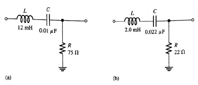
FIGURE 13-70
Assuming that the coils in Figure 13-70 have a winding resistance of
Expert Solution & Answer
Want to see the full answer?
Check out a sample textbook solution
Students have asked these similar questions
18. A triangular waveform with a peak-to-peak voltage of 2 V and a period of I ms is applied to
the differentiator in Figure 13–70(a). What is the output voltage?
洋SV
15 k)
10 µF
10
10 kM
0.047 µF
(b)
()
Aetivate Wndew
FIGURE 13-70
16. A triangular waveform is applied to the input of the circuit in Figure 13-69 as shown.
Determine what the output should be and sketch its waveform in relation to the input.
R
5 V
10 kQ
10 μs.
0.001 µF
out
Activat
Go to Set
FIGURE 13-61
+
R1
47 k2
R,
18 k2
3. Calculate the VUTP and V1TP in Figure 13-61. V
out(max)
= +10 V.
4. What is the hysteresis voltage in Figure 13-61?
5. Draw the output voltage waveform for each circuit in Figure 13-62 with respect to the input.
Show voltage levels.
Chapter 13 Solutions
Electronics Fundamentals: Circuits, Devices & Applications
Ch. 13 - A series RLC circuit can have a higher voltage...Ch. 13 - The impedance of a series RLC circuit is dependent...Ch. 13 - Above the resonant frequency, series resonant...Ch. 13 - Prob. 4TFQCh. 13 - Prob. 5TFQCh. 13 - The upper and lower cutoff frequencies of a...Ch. 13 - Prob. 7TFQCh. 13 - The Q of a band-pass filter does not affect the...Ch. 13 - Prob. 9TFQCh. 13 - Prob. 10TFQ
Ch. 13 - Prob. 1STCh. 13 - The phase angle of a series RLC circuit at...Ch. 13 - The impedance at the resonant frequency of a...Ch. 13 - In a series RLC circuit that is operating below...Ch. 13 - Prob. 5STCh. 13 - Prob. 6STCh. 13 - Prob. 7STCh. 13 - Prob. 8STCh. 13 - Prob. 9STCh. 13 - Prob. 10STCh. 13 - Prob. 11STCh. 13 - Prob. 12STCh. 13 - A certain series RLC circuit operates at a...Ch. 13 - Find the impedance in Figure 13-66.Ch. 13 - If the frequency of the source voltage in Figure...Ch. 13 - For the circuit in figure 13-66, find Itot,VR,VL,...Ch. 13 - Draw the voltage phasor diagram for the circuit in...Ch. 13 - Analyze the circuit in Figure 13-67 for the...Ch. 13 - For the circuit in Figure 13-66, is the resonant...Ch. 13 - For the circuit in Figure 13-68, determine the...Ch. 13 - Find XL,XC,Z, and I at the resonant frequency in...Ch. 13 - A certain series resonant circuit has a maximum...Ch. 13 - For the RLC circuit in Figure 13-69, determine the...Ch. 13 - What is the value of the current at the half-power...Ch. 13 - Determine the resonant frequency for each filter...Ch. 13 - FIGURE 13-70 Assuming that the coils in Figure...Ch. 13 - Determine fr and BW for each filter in Figure...Ch. 13 - Find the total impedance of the circuit in Figure...Ch. 13 - Is the circuit in Figure 13-72 capacitive or...Ch. 13 - For the circuit in Figure 13-72, find all the...Ch. 13 - Find the total impedence for the circuit in Figure...Ch. 13 - What is the impedance of an ideal parallel...Ch. 13 - Prob. 21PCh. 13 - How much current is drawn from the source in...Ch. 13 - At resonance, XL=2K and RW=25 in a parallel...Ch. 13 - If the lower cutoff frequency is 2400 Hz and the...Ch. 13 - In a certain resonant circuit, the power to the...Ch. 13 - What values of L and C should be used in a tank...Ch. 13 - Prob. 27PCh. 13 - A parallel resonant band-stop filter is needed to...Ch. 13 - Prob. 29PCh. 13 - Prob. 30PCh. 13 - Prob. 31PCh. 13 - Determine whether there is a value of C that will...Ch. 13 - If the value of C is 0.22F, how much current is...Ch. 13 - Determine the resonant frequencies in Figure 13-77...Ch. 13 - Prob. 35PCh. 13 - Prob. 36PCh. 13 - Prob. 37PCh. 13 - Prob. 39PCh. 13 - Prob. 40PCh. 13 - Prob. 41PCh. 13 - Open file P13-42. Determine if there is a fault...Ch. 13 - Prob. 43P
Knowledge Booster


Learn more about
Need a deep-dive on the concept behind this application? Look no further. Learn more about this topic, electrical-engineering and related others by exploring similar questions and additional content below.Similar questions
- FIGURE 13-66 R +1 Vo W 22 k. 22 kQ R2 +1.8 VoW OUT 22 k) 11. Find the value of Rf necessary to produce an output that is five times the sum of the inputs in Figure 13-66.arrow_forwardWhat is the lower cutoff frequency due to C, C2 and C3 for circuit in figure 1? Assume re = 4.5 ohm and Beta = 200. 10ka 10 F 2N3904 10 pF 100 Ra 47 ka 1330a 47 pFarrow_forwardCalculate circuit values below. Does the cuicuit change from a lead circuit to a lag circuit as the frequency increases from 500 HZ to 50 Khz?arrow_forward
- For each of the cascaded counter configurations in Figure below, determine the frequency of the waveform at each point indicated by a circled number, and determine the overall modulus. I kHz DIV 4 DIV 8 DIV 2 (a) DIV 10 DIV 10 DIV 10 DIV 2 100 kHz (b)arrow_forwardAn impedance has a resistance of 60 ohms and an inductance of 0.144 henry. What series combination of R and C should be connected in parallel with the coil to make the circuit resonant at all frequencies?arrow_forwardUsually, a multistage amplifier connection can be used to increase the overall small-signal voltage gain and to provideoutput impedance. A very high B) zero (c) infinite D) very lowarrow_forward
- The input voltage to chopper circuit with a switching frequency of 100 Hz and TOn time as 2.0 ms is 10 V. The average DC output is: O 4V O 2V O 6V O 8Varrow_forwardCalculate circuit values below. How does the total circuit impedence change as the frequency increases from 500 HZ to 50 Khz? How does the total current change as those frequencies increase?arrow_forwardExercise: Consider the series RLC circuit of Figure 1 with the source a 1-kHz sinusoid having an amplitude of 5 V. Regard the source voltage as having zero phase. Calculate the amplitude and phase (in degrees) of the following quantities: the voltage across the resistor, the voltage across the inductor, and the voltage across the capacitorarrow_forward
- 2. Determine the output level (maximum positive or maxiimum negative)) for each comparator in Figure 13-60. 7 Vo Vaur SV= (C) IGURE 13-60arrow_forward3) Pure Inductance in Series Frequency = 60HZ EL1 = E2 = E13 = %3D ET = 2kVarrow_forwardDetermine the total inductance of each circuit in Figure 13-50arrow_forward
arrow_back_ios
SEE MORE QUESTIONS
arrow_forward_ios
Recommended textbooks for you
 Introductory Circuit Analysis (13th Edition)Electrical EngineeringISBN:9780133923605Author:Robert L. BoylestadPublisher:PEARSON
 Delmar's Standard Textbook Of ElectricityElectrical EngineeringISBN:9781337900348Author:Stephen L. HermanPublisher:Cengage Learning
 Programmable Logic ControllersElectrical EngineeringISBN:9780073373843Author:Frank D. PetruzellaPublisher:McGraw-Hill Education
 Fundamentals of Electric CircuitsElectrical EngineeringISBN:9780078028229Author:Charles K Alexander, Matthew SadikuPublisher:McGraw-Hill Education
 Electric Circuits. (11th Edition)Electrical EngineeringISBN:9780134746968Author:James W. Nilsson, Susan RiedelPublisher:PEARSON
 Engineering ElectromagneticsElectrical EngineeringISBN:9780078028151Author:Hayt, William H. (william Hart), Jr, BUCK, John A.Publisher:Mcgraw-hill Education,
Introductory Circuit Analysis (13th Edition)
Electrical Engineering
ISBN:9780133923605
Author:Robert L. Boylestad
Publisher:PEARSON
Delmar's Standard Textbook Of Electricity
Electrical Engineering
ISBN:9781337900348
Author:Stephen L. Herman
Publisher:Cengage Learning
Programmable Logic Controllers
Electrical Engineering
ISBN:9780073373843
Author:Frank D. Petruzella
Publisher:McGraw-Hill Education
Fundamentals of Electric Circuits
Electrical Engineering
ISBN:9780078028229
Author:Charles K Alexander, Matthew Sadiku
Publisher:McGraw-Hill Education
Electric Circuits. (11th Edition)
Electrical Engineering
ISBN:9780134746968
Author:James W. Nilsson, Susan Riedel
Publisher:PEARSON
Engineering Electromagnetics
Electrical Engineering
ISBN:9780078028151
Author:Hayt, William H. (william Hart), Jr, BUCK, John A.
Publisher:Mcgraw-hill Education,
Capacitors Explained - The basics how capacitors work working principle; Author: The Engineering Mindset;https://www.youtube.com/watch?v=X4EUwTwZ110;License: Standard YouTube License, CC-BY