
Electronics Fundamentals: Circuits, Devices & Applications
8th Edition
ISBN: 9780135072950
Author: Thomas L. Floyd, David Buchla
Publisher: Prentice Hall
expand_more
expand_more
format_list_bulleted
Videos
Textbook Question
Chapter 13, Problem 13P
Determine the resonant frequency for each filter in Figure 13-70. Are these filters band-pass or band-stop types?
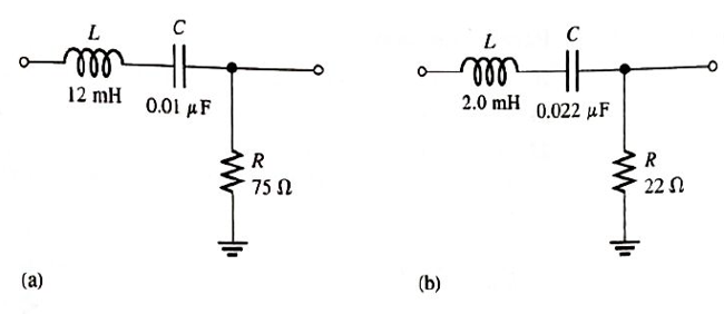
FIGURE 13-70
Expert Solution & Answer
Want to see the full answer?
Check out a sample textbook solution
Students have asked these similar questions
18. A triangular waveform with a peak-to-peak voltage of 2 V and a period of I ms is applied to
the differentiator in Figure 13–70(a). What is the output voltage?
洋SV
15 k)
10 µF
10
10 kM
0.047 µF
(b)
()
Aetivate Wndew
FIGURE 13-70
8. Determine the output voltage waveform in Figure 13-64
D2
4.7 V
4.7 V
+3 V
R1
47 k
-3 V
our
R
47 k!
Ry
10 k
+
For each of the cascaded counter
configurations in Figure below, determine the
frequency of the waveform at each point
indicated by a circled number, and determine
the overall modulus.
I kHz
DIV 4
DIV 8
DIV 2
(a)
DIV 10
DIV 10
DIV 10
DIV 2
100 kHz
(b)
Chapter 13 Solutions
Electronics Fundamentals: Circuits, Devices & Applications
Ch. 13 - A series RLC circuit can have a higher voltage...Ch. 13 - The impedance of a series RLC circuit is dependent...Ch. 13 - Above the resonant frequency, series resonant...Ch. 13 - Prob. 4TFQCh. 13 - Prob. 5TFQCh. 13 - The upper and lower cutoff frequencies of a...Ch. 13 - Prob. 7TFQCh. 13 - The Q of a band-pass filter does not affect the...Ch. 13 - Prob. 9TFQCh. 13 - Prob. 10TFQ
Ch. 13 - Prob. 1STCh. 13 - The phase angle of a series RLC circuit at...Ch. 13 - The impedance at the resonant frequency of a...Ch. 13 - In a series RLC circuit that is operating below...Ch. 13 - Prob. 5STCh. 13 - Prob. 6STCh. 13 - Prob. 7STCh. 13 - Prob. 8STCh. 13 - Prob. 9STCh. 13 - Prob. 10STCh. 13 - Prob. 11STCh. 13 - Prob. 12STCh. 13 - A certain series RLC circuit operates at a...Ch. 13 - Find the impedance in Figure 13-66.Ch. 13 - If the frequency of the source voltage in Figure...Ch. 13 - For the circuit in figure 13-66, find Itot,VR,VL,...Ch. 13 - Draw the voltage phasor diagram for the circuit in...Ch. 13 - Analyze the circuit in Figure 13-67 for the...Ch. 13 - For the circuit in Figure 13-66, is the resonant...Ch. 13 - For the circuit in Figure 13-68, determine the...Ch. 13 - Find XL,XC,Z, and I at the resonant frequency in...Ch. 13 - A certain series resonant circuit has a maximum...Ch. 13 - For the RLC circuit in Figure 13-69, determine the...Ch. 13 - What is the value of the current at the half-power...Ch. 13 - Determine the resonant frequency for each filter...Ch. 13 - FIGURE 13-70 Assuming that the coils in Figure...Ch. 13 - Determine fr and BW for each filter in Figure...Ch. 13 - Find the total impedance of the circuit in Figure...Ch. 13 - Is the circuit in Figure 13-72 capacitive or...Ch. 13 - For the circuit in Figure 13-72, find all the...Ch. 13 - Find the total impedence for the circuit in Figure...Ch. 13 - What is the impedance of an ideal parallel...Ch. 13 - Prob. 21PCh. 13 - How much current is drawn from the source in...Ch. 13 - At resonance, XL=2K and RW=25 in a parallel...Ch. 13 - If the lower cutoff frequency is 2400 Hz and the...Ch. 13 - In a certain resonant circuit, the power to the...Ch. 13 - What values of L and C should be used in a tank...Ch. 13 - Prob. 27PCh. 13 - A parallel resonant band-stop filter is needed to...Ch. 13 - Prob. 29PCh. 13 - Prob. 30PCh. 13 - Prob. 31PCh. 13 - Determine whether there is a value of C that will...Ch. 13 - If the value of C is 0.22F, how much current is...Ch. 13 - Determine the resonant frequencies in Figure 13-77...Ch. 13 - Prob. 35PCh. 13 - Prob. 36PCh. 13 - Prob. 37PCh. 13 - Prob. 39PCh. 13 - Prob. 40PCh. 13 - Prob. 41PCh. 13 - Open file P13-42. Determine if there is a fault...Ch. 13 - Prob. 43P
Knowledge Booster


Learn more about
Need a deep-dive on the concept behind this application? Look no further. Learn more about this topic, electrical-engineering and related others by exploring similar questions and additional content below.Similar questions
- 2. Determine the output level (maximum positive or maxiimum negative)) for each comparator in Figure 13-60. 7 Vo Vaur SV= (C) IGURE 13-60arrow_forwardWhat capacitance value is required for each of the varactors in the following figure to produce a resonant frequency of 1 MHz? VRO- D₁ D₂ 000111 2 mHarrow_forwardQ7/ Draw the output waveform of the differentiator whose R=1M, and C=100µf for the input waveform shown below (the duty cycle is 50%). VIN 10μsecond Your answer Q8/ Please send your answers in a single pdf file ONLY * 1 Add file Page 1 of 1 Submit Alouar oihmit n uerde threushCaal. Formearrow_forward
- H: A 4V peak sine wave is fed to the circuit and a 1V peak sine wave results. Determine the gain in units of db. Va R1 ww Vb T C1 Gain Frequencyarrow_forwardRefer to the parallel resonant circuit of Figure 21-41. 2 μAZ0 R 220 pF fp = 800 kHz BW = 25 kHz FIGURE 21-41 Suppose the circuit has a resonant frequency of 800 kHz and a bandwidth of 25 kHz. a. Determine the value of the inductor, L, in henries. b. Calculate the value of the resistance, R, in ohms. c. Find V, IL, and power, P, at resonance. d. Find the approximate values of the half-power frequencies, fi and f2. e. Determine the voltage across the circuit at the lower half-power frequency, fi, and show that the power dissipated by the resistor at this frequency is half the power dissipated at the resonant frequency. + LV I Ⓒ Cengage Learning 2013arrow_forwardCI Meet - asw-dpwm-hkn O X + UpBoyZQXsj09MBELppNe5Nv3cHTKK4uB7uCr2hEkfwlw/formResponse Find the value of Cext for the following oscillator, cutoff frequency =25kHz +5,5 V RESET |DISCH 555 THRESH OUT TRIG CONT GND 0 01 µF 7.57UF O 0.01UF O 7.57NF O 0.047UF Oarrow_forward
- What will be the output voltage of Low pass filter if the resistance value is 3.7 kilo ohm, capacitance value is 20 nano farad and input voltage applied is 8.6V. Frequency is 500 Hz.arrow_forward16. A triangular waveform is applied to the input of the circuit in Figure 13-69 as shown. Determine what the output should be and sketch its waveform in relation to the input. R 5 V 10 kQ 10 μs. 0.001 µF out Activat Go to Setarrow_forwardResonent circuitarrow_forward
- 11) Refer to the figure Low frequency response is affected by A) CBE B) C3 C) Re D) All of the abovearrow_forwardExercise: Consider the series RLC circuit of Figure 1 with the source a 1-kHz sinusoid having an amplitude of 5 V. Regard the source voltage as having zero phase. Calculate the amplitude and phase (in degrees) of the following quantities: the voltage across the resistor, the voltage across the inductor, and the voltage across the capacitorarrow_forwardA step up chopper delivers a 2A current to the 10ohm load. The input voltage is 100V, L=1mH with chopper frequency of 10kHz. Determine the maximum and minimum current at the outputarrow_forward
arrow_back_ios
SEE MORE QUESTIONS
arrow_forward_ios
Recommended textbooks for you
 Introductory Circuit Analysis (13th Edition)Electrical EngineeringISBN:9780133923605Author:Robert L. BoylestadPublisher:PEARSON
 Delmar's Standard Textbook Of ElectricityElectrical EngineeringISBN:9781337900348Author:Stephen L. HermanPublisher:Cengage Learning
 Programmable Logic ControllersElectrical EngineeringISBN:9780073373843Author:Frank D. PetruzellaPublisher:McGraw-Hill Education
 Fundamentals of Electric CircuitsElectrical EngineeringISBN:9780078028229Author:Charles K Alexander, Matthew SadikuPublisher:McGraw-Hill Education
 Electric Circuits. (11th Edition)Electrical EngineeringISBN:9780134746968Author:James W. Nilsson, Susan RiedelPublisher:PEARSON
 Engineering ElectromagneticsElectrical EngineeringISBN:9780078028151Author:Hayt, William H. (william Hart), Jr, BUCK, John A.Publisher:Mcgraw-hill Education,
Introductory Circuit Analysis (13th Edition)
Electrical Engineering
ISBN:9780133923605
Author:Robert L. Boylestad
Publisher:PEARSON
Delmar's Standard Textbook Of Electricity
Electrical Engineering
ISBN:9781337900348
Author:Stephen L. Herman
Publisher:Cengage Learning
Programmable Logic Controllers
Electrical Engineering
ISBN:9780073373843
Author:Frank D. Petruzella
Publisher:McGraw-Hill Education
Fundamentals of Electric Circuits
Electrical Engineering
ISBN:9780078028229
Author:Charles K Alexander, Matthew Sadiku
Publisher:McGraw-Hill Education
Electric Circuits. (11th Edition)
Electrical Engineering
ISBN:9780134746968
Author:James W. Nilsson, Susan Riedel
Publisher:PEARSON
Engineering Electromagnetics
Electrical Engineering
ISBN:9780078028151
Author:Hayt, William H. (william Hart), Jr, BUCK, John A.
Publisher:Mcgraw-hill Education,
02 - Sinusoidal AC Voltage Sources in Circuits, Part 1; Author: Math and Science;https://www.youtube.com/watch?v=8zMiIHVMfaw;License: Standard Youtube License