
Introductory Circuit Analysis (13th Edition)
13th Edition
ISBN: 9780133923605
Author: Robert L. Boylestad
Publisher: PEARSON
expand_more
expand_more
format_list_bulleted
Related questions
Concept explainers
Question
thumb_up100%
Calculate circuit values below. How does the total circuit impedence change as the frequency increases from 500 HZ to 50 Khz? How does the total current change as those frequencies increase?
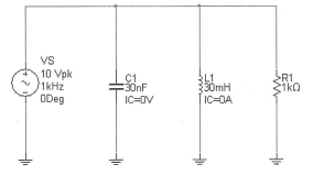

Transcribed Image Text:### Circuit Diagram Description
The schematic diagram displayed is a simple RLC (Resistor-Inductor-Capacitor) series circuit. It contains the following components:
1. **Voltage Source (VS):**
- **Value:** 10 Volts peak (Vpk)
- **Frequency:** 1 kHz
- **Phase:** 0 degrees
- The source provides an AC signal at 1 kHz with a peak voltage of 10 volts, starting at 0 degrees phase angle.
2. **Capacitor (C1):**
- **Capacitance:** 30 nanoFarads (nF)
- **Initial Condition (IC):** 0 Volts (V)
- The capacitor is initially uncharged.
3. **Inductor (L1):**
- **Inductance:** 30 milliHenries (mH)
- **Initial Condition (IC):** 0 Amperes (A)
- The inductor has no initial current flowing through it.
4. **Resistor (R1):**
- **Resistance:** 1 kiloOhm (kΩ)
- The resistor provides a constant resistance to the AC circuit.
### Explanation
This RLC circuit is commonly used to study the behavior of AC circuits with reactive components (inductors and capacitors). Key characteristics such as impedance, phase angle, and resonance can be analyzed using such a setup. Understanding these interactions is crucial in designing circuits for various applications in electronics and communication systems.

Transcribed Image Text:**Circuit Analysis Table**
This table provides a structured approach to analyzing a circuit at different frequencies, specifically 500 Hz, 5 kHz, and 50 kHz. It lists the following parameters and equations:
- **\( X_{L1} \)**: Inductive reactance
- **\( X_{C1} \)**: Capacitive reactance
- **\( I_{R1} = V_S / R_1 \)**: Current through the resistor
- **\( I_{L1} = V_S / X_{L1} \)**: Current through the inductor
- **\( I_{C1} = V_S / X_{C1} \)**: Current through the capacitor
- **\( I_T = I_{R1} + j(I_{C1} - I_{L1}) \)**: Total current in the circuit, accounting for phase differences
- **\( Z_T = V_S / I_T \)**: Total impedance of the circuit
This table does not contain specific numerical values but leaves space to calculate and fill in these values at each specified frequency. This allows for analysis of how the circuit behavior changes as the frequency varies.
Expert Solution
This question has been solved!
Explore an expertly crafted, step-by-step solution for a thorough understanding of key concepts.

This is a popular solution

Trending nowThis is a popular solution!

Step by stepSolved in 5 steps with 35 images

Knowledge Booster


Learn more about
Need a deep-dive on the concept behind this application? Look no further. Learn more about this topic, electrical-engineering and related others by exploring similar questions and additional content below.Similar questions
- Suppose that at any given time t (in seconds) the current i (in amperes) in an alternating current circuit is i= cost + sint. What is the peak current for this circuit (largest magnitude)? The peak current for this circuit is amperes. (Type an exact answer, using radicals as needed.)arrow_forwardPlease solve the marked question.arrow_forwardWhat is simeconductorarrow_forward
arrow_back_ios
arrow_forward_ios
Recommended textbooks for you
- Introductory Circuit Analysis (13th Edition)Electrical EngineeringISBN:9780133923605Author:Robert L. BoylestadPublisher:PEARSON
 Delmar's Standard Textbook Of ElectricityElectrical EngineeringISBN:9781337900348Author:Stephen L. HermanPublisher:Cengage Learning
 Programmable Logic ControllersElectrical EngineeringISBN:9780073373843Author:Frank D. PetruzellaPublisher:McGraw-Hill Education
  Fundamentals of Electric CircuitsElectrical EngineeringISBN:9780078028229Author:Charles K Alexander, Matthew SadikuPublisher:McGraw-Hill Education
 Electric Circuits. (11th Edition)Electrical EngineeringISBN:9780134746968Author:James W. Nilsson, Susan RiedelPublisher:PEARSON
 Engineering ElectromagneticsElectrical EngineeringISBN:9780078028151Author:Hayt, William H. (william Hart), Jr, BUCK, John A.Publisher:Mcgraw-hill Education,
Introductory Circuit Analysis (13th Edition)
Electrical Engineering
ISBN:9780133923605
Author:Robert L. Boylestad
Publisher:PEARSON
Delmar's Standard Textbook Of Electricity
Electrical Engineering
ISBN:9781337900348
Author:Stephen L. Herman
Publisher:Cengage Learning
Programmable Logic Controllers
Electrical Engineering
ISBN:9780073373843
Author:Frank D. Petruzella
Publisher:McGraw-Hill Education
Fundamentals of Electric Circuits
Electrical Engineering
ISBN:9780078028229
Author:Charles K Alexander, Matthew Sadiku
Publisher:McGraw-Hill Education
Electric Circuits. (11th Edition)
Electrical Engineering
ISBN:9780134746968
Author:James W. Nilsson, Susan Riedel
Publisher:PEARSON
Engineering Electromagnetics
Electrical Engineering
ISBN:9780078028151
Author:Hayt, William H. (william Hart), Jr, BUCK, John A.
Publisher:Mcgraw-hill Education,