
Electronics Fundamentals: Circuits, Devices & Applications
8th Edition
ISBN: 9780135072950
Author: Thomas L. Floyd, David Buchla
Publisher: Prentice Hall
expand_more
expand_more
format_list_bulleted
Concept explainers
Videos
Textbook Question
Chapter 13, Problem 3P
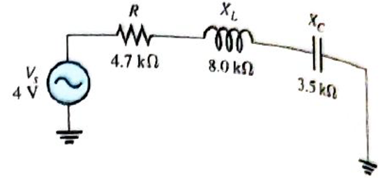
If the frequency of the source voltage in Figure 13-66 is doubled from the value that produces the indicated reactances, how does the impedance change?
Expert Solution & Answer
Want to see the full answer?
Check out a sample textbook solution
Students have asked these similar questions
A 47-ohms load resistor is connected in series with a 10-uF capacitor. At what frequency will the capacitor reach the same value as the load resistor?
What will be magnitude of the total circuit impedance of a series LR circuit excited by a 100 Hz ac source? The resistance is 40 ohm and the inductance is 4 mF.
n 12
For the given waveforms, waveform D
the waveform E.
put of
-D
uestion
Degrees
30 60 90
180 210
360
N.
In a step down transformer, number of turns in the primary winding is lesser than the number of turns in the
secondary winding.
Select one:
O True
en
O False
nere to search
Chapter 13 Solutions
Electronics Fundamentals: Circuits, Devices & Applications
Ch. 13 - A series RLC circuit can have a higher voltage...Ch. 13 - The impedance of a series RLC circuit is dependent...Ch. 13 - Above the resonant frequency, series resonant...Ch. 13 - Prob. 4TFQCh. 13 - Prob. 5TFQCh. 13 - The upper and lower cutoff frequencies of a...Ch. 13 - Prob. 7TFQCh. 13 - The Q of a band-pass filter does not affect the...Ch. 13 - Prob. 9TFQCh. 13 - Prob. 10TFQ
Ch. 13 - Prob. 1STCh. 13 - The phase angle of a series RLC circuit at...Ch. 13 - The impedance at the resonant frequency of a...Ch. 13 - In a series RLC circuit that is operating below...Ch. 13 - Prob. 5STCh. 13 - Prob. 6STCh. 13 - Prob. 7STCh. 13 - Prob. 8STCh. 13 - Prob. 9STCh. 13 - Prob. 10STCh. 13 - Prob. 11STCh. 13 - Prob. 12STCh. 13 - A certain series RLC circuit operates at a...Ch. 13 - Find the impedance in Figure 13-66.Ch. 13 - If the frequency of the source voltage in Figure...Ch. 13 - For the circuit in figure 13-66, find Itot,VR,VL,...Ch. 13 - Draw the voltage phasor diagram for the circuit in...Ch. 13 - Analyze the circuit in Figure 13-67 for the...Ch. 13 - For the circuit in Figure 13-66, is the resonant...Ch. 13 - For the circuit in Figure 13-68, determine the...Ch. 13 - Find XL,XC,Z, and I at the resonant frequency in...Ch. 13 - A certain series resonant circuit has a maximum...Ch. 13 - For the RLC circuit in Figure 13-69, determine the...Ch. 13 - What is the value of the current at the half-power...Ch. 13 - Determine the resonant frequency for each filter...Ch. 13 - FIGURE 13-70 Assuming that the coils in Figure...Ch. 13 - Determine fr and BW for each filter in Figure...Ch. 13 - Find the total impedance of the circuit in Figure...Ch. 13 - Is the circuit in Figure 13-72 capacitive or...Ch. 13 - For the circuit in Figure 13-72, find all the...Ch. 13 - Find the total impedence for the circuit in Figure...Ch. 13 - What is the impedance of an ideal parallel...Ch. 13 - Prob. 21PCh. 13 - How much current is drawn from the source in...Ch. 13 - At resonance, XL=2K and RW=25 in a parallel...Ch. 13 - If the lower cutoff frequency is 2400 Hz and the...Ch. 13 - In a certain resonant circuit, the power to the...Ch. 13 - What values of L and C should be used in a tank...Ch. 13 - Prob. 27PCh. 13 - A parallel resonant band-stop filter is needed to...Ch. 13 - Prob. 29PCh. 13 - Prob. 30PCh. 13 - Prob. 31PCh. 13 - Determine whether there is a value of C that will...Ch. 13 - If the value of C is 0.22F, how much current is...Ch. 13 - Determine the resonant frequencies in Figure 13-77...Ch. 13 - Prob. 35PCh. 13 - Prob. 36PCh. 13 - Prob. 37PCh. 13 - Prob. 39PCh. 13 - Prob. 40PCh. 13 - Prob. 41PCh. 13 - Open file P13-42. Determine if there is a fault...Ch. 13 - Prob. 43P
Knowledge Booster


Learn more about
Need a deep-dive on the concept behind this application? Look no further. Learn more about this topic, electrical-engineering and related others by exploring similar questions and additional content below.Similar questions
- What is the total reactance in Figure 13-2? 2.0 H 60 Hz 37.68 Ohms 753.6 Ohms 376.8 Ohms Figure 13 - 2 O 3,760.8 Ohms 2.0 Harrow_forwardShow the voltage waveforms across each half of the secondary winding and across RL. Find the average value of the full-wave rectified voltage in Figure. 120 Vrms elller 4:1 reetee D₁ RL 1.0 ΚΩarrow_forwardDetermine the total inductance of each circuit in Figure 13-50arrow_forward
- When a capacitor is discharged through a resistor, the discharge curve is exponential Sinusoidal Step Squarearrow_forwardCalibri (Body) -11 by AaBbCcDx AaBbCcD AaBbC AaBbCc AaB AaBbCc. mat Painter BIU 1Normal 1No Spaci. Heading 1 Heading 2 Title Subtitle Chang Styles d Font Paragraph Styles IMPEDANCE QUIZ # 2 1. What capacitance when connected in series with a 500Q resistor will limit the current drawn from a 48-mV 465-kHz source to 20µA? * a. 144pF b. 145pF c. 146pF d. 147pF MY ANSWER: c.146pF 2. What is the total impedance at 20kHz of a series circuit consisting of a 1.5mH inductance, a 100Q resistance, and a 0.08uF capacitance? * a. 1340 41.7 b. 1930 L-37.2" C. 920 290 d. 530 2-12.6°arrow_forwardPlease solve fast ,Have very less time. Do correctly . What is the total inductance in the circuit in Figure 13-1? A) 2600 uH B) 2100 mH C) 602 mH D) 800 mHarrow_forward
- 8. Determine the output voltage waveform in Figure 13-64 D2 4.7 V 4.7 V +3 V R1 47 k -3 V our R 47 k! Ry 10 k +arrow_forwardQ6) The waveform of the voltage obtained after rectification is of a -----nature and therefore contains .harmonics a. Sinusoidal O b. Triangular c. Pulsating O d. Repetitive Oarrow_forward8. Determine the output voltage waveform in Figure 13-64. D, D2 +3 V 4.7 V 4.7 V R1 47 k2 O V qut -3 V R2 47 kN R3 10 kNarrow_forward
- the shunt capacitance is a capacitor O a. Between a phase and the ground O b. between phases and a phase to ground c. none of the answers O d. Between phasesarrow_forward16. A triangular waveform is applied to the input of the circuit in Figure 13-69 as shown. Determine what the output should be and sketch its waveform in relation to the input. R 5 V 10 kQ 10 μs. 0.001 µF out Activat Go to Setarrow_forwardeating in the thondy voltoge The netuork show in ope state wilh sinussidal vo and V, 2 Sinzt delermine the voltafe Va(t) 2178 F Va 2178F 2173F IHarrow_forward
arrow_back_ios
SEE MORE QUESTIONS
arrow_forward_ios
Recommended textbooks for you
 Electricity for Refrigeration, Heating, and Air C...Mechanical EngineeringISBN:9781337399128Author:Russell E. SmithPublisher:Cengage Learning
 Delmar's Standard Textbook Of ElectricityElectrical EngineeringISBN:9781337900348Author:Stephen L. HermanPublisher:Cengage Learning
Electricity for Refrigeration, Heating, and Air C...
Mechanical Engineering
ISBN:9781337399128
Author:Russell E. Smith
Publisher:Cengage Learning
Delmar's Standard Textbook Of Electricity
Electrical Engineering
ISBN:9781337900348
Author:Stephen L. Herman
Publisher:Cengage Learning
Understanding Frequency Modulation; Author: Rohde Schwarz;https://www.youtube.com/watch?v=gFu7-7lUGDg;License: Standard Youtube License