
Electronics Fundamentals: Circuits, Devices & Applications
8th Edition
ISBN: 9780135072950
Author: Thomas L. Floyd, David Buchla
Publisher: Prentice Hall
expand_more
expand_more
format_list_bulleted
Concept explainers
Videos
Textbook Question
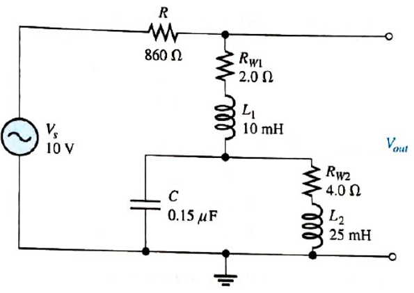
Chapter 13, Problem 34P
Determine the resonant frequencies in Figure 13-77 and find
Expert Solution & Answer
Want to see the full answer?
Check out a sample textbook solution
Students have asked these similar questions
For each of the cascaded counter
configurations in Figure below, determine the
frequency of the waveform at each point
indicated by a circled number, and determine
the overall modulus.
I kHz
DIV 4
DIV 8
DIV 2
(a)
DIV 10
DIV 10
DIV 10
DIV 2
100 kHz
(b)
8. Determine the output voltage waveform in Figure 13-64
D2
4.7 V
4.7 V
+3 V
R1
47 k
-3 V
our
R
47 k!
Ry
10 k
+
18. A triangular waveform with a peak-to-peak voltage of 2 V and a period of I ms is applied to
the differentiator in Figure 13–70(a). What is the output voltage?
洋SV
15 k)
10 µF
10
10 kM
0.047 µF
(b)
()
Aetivate Wndew
FIGURE 13-70
Chapter 13 Solutions
Electronics Fundamentals: Circuits, Devices & Applications
Ch. 13 - A series RLC circuit can have a higher voltage...Ch. 13 - The impedance of a series RLC circuit is dependent...Ch. 13 - Above the resonant frequency, series resonant...Ch. 13 - Prob. 4TFQCh. 13 - Prob. 5TFQCh. 13 - The upper and lower cutoff frequencies of a...Ch. 13 - Prob. 7TFQCh. 13 - The Q of a band-pass filter does not affect the...Ch. 13 - Prob. 9TFQCh. 13 - Prob. 10TFQ
Ch. 13 - Prob. 1STCh. 13 - The phase angle of a series RLC circuit at...Ch. 13 - The impedance at the resonant frequency of a...Ch. 13 - In a series RLC circuit that is operating below...Ch. 13 - Prob. 5STCh. 13 - Prob. 6STCh. 13 - Prob. 7STCh. 13 - Prob. 8STCh. 13 - Prob. 9STCh. 13 - Prob. 10STCh. 13 - Prob. 11STCh. 13 - Prob. 12STCh. 13 - A certain series RLC circuit operates at a...Ch. 13 - Find the impedance in Figure 13-66.Ch. 13 - If the frequency of the source voltage in Figure...Ch. 13 - For the circuit in figure 13-66, find Itot,VR,VL,...Ch. 13 - Draw the voltage phasor diagram for the circuit in...Ch. 13 - Analyze the circuit in Figure 13-67 for the...Ch. 13 - For the circuit in Figure 13-66, is the resonant...Ch. 13 - For the circuit in Figure 13-68, determine the...Ch. 13 - Find XL,XC,Z, and I at the resonant frequency in...Ch. 13 - A certain series resonant circuit has a maximum...Ch. 13 - For the RLC circuit in Figure 13-69, determine the...Ch. 13 - What is the value of the current at the half-power...Ch. 13 - Determine the resonant frequency for each filter...Ch. 13 - FIGURE 13-70 Assuming that the coils in Figure...Ch. 13 - Determine fr and BW for each filter in Figure...Ch. 13 - Find the total impedance of the circuit in Figure...Ch. 13 - Is the circuit in Figure 13-72 capacitive or...Ch. 13 - For the circuit in Figure 13-72, find all the...Ch. 13 - Find the total impedence for the circuit in Figure...Ch. 13 - What is the impedance of an ideal parallel...Ch. 13 - Prob. 21PCh. 13 - How much current is drawn from the source in...Ch. 13 - At resonance, XL=2K and RW=25 in a parallel...Ch. 13 - If the lower cutoff frequency is 2400 Hz and the...Ch. 13 - In a certain resonant circuit, the power to the...Ch. 13 - What values of L and C should be used in a tank...Ch. 13 - Prob. 27PCh. 13 - A parallel resonant band-stop filter is needed to...Ch. 13 - Prob. 29PCh. 13 - Prob. 30PCh. 13 - Prob. 31PCh. 13 - Determine whether there is a value of C that will...Ch. 13 - If the value of C is 0.22F, how much current is...Ch. 13 - Determine the resonant frequencies in Figure 13-77...Ch. 13 - Prob. 35PCh. 13 - Prob. 36PCh. 13 - Prob. 37PCh. 13 - Prob. 39PCh. 13 - Prob. 40PCh. 13 - Prob. 41PCh. 13 - Open file P13-42. Determine if there is a fault...Ch. 13 - Prob. 43P
Additional Engineering Textbook Solutions
Find more solutions based on key concepts
The voltage source of the circuit shown in Fig. P1.29 is given by s(t)=25cos(4104t45)(V). Obtain an expression ...
Fundamentals of Applied Electromagnetics (7th Edition)
Three point charges of equal magnitude q, that will yield a zero net electric field at the origin.
Engineering Electromagnetics
Design an ideal inverting op-amp circuit such that the voltage gain is Av=25 . The maximum current in any resis...
Microelectronics: Circuit Analysis and Design
When travelers from the USA and Canada visit Europe, they encounter a different power distribution system. Wall...
Electric machinery fundamentals
Assume a telephone signal travels through a cable at two-thirds the speed of light. How long does it take the s...
Electric Circuits (10th Edition)
Electric power systems provide energy in a variety of commercial and industrial settings. Make a list of system...
Principles and Applications of Electrical Engineering
Knowledge Booster


Learn more about
Need a deep-dive on the concept behind this application? Look no further. Learn more about this topic, electrical-engineering and related others by exploring similar questions and additional content below.Similar questions
- 16. A triangular waveform is applied to the input of the circuit in Figure 13-69 as shown. Determine what the output should be and sketch its waveform in relation to the input. R 5 V 10 kQ 10 μs. 0.001 µF out Activat Go to Setarrow_forwardWhat capacitance value is required for each of the varactors in the following figure to produce a resonant frequency of 1 MHz? VRO- D₁ D₂ 000111 2 mHarrow_forwardH: A 4V peak sine wave is fed to the circuit and a 1V peak sine wave results. Determine the gain in units of db. Va R1 ww Vb T C1 Gain Frequencyarrow_forward
- Thus, in the verden circuit IG = 2.00uA is an 8.00kHz sine sign with a peak-to-peak value, L1 = 3.00uA Rs=3.34Kohm, R1 5.12Kohm. R2=3548.67Kohm, R3 =8.73Kohm, R4 =2.16Kohm R5 =23.17Kohm, VCC =11.00V, VEE--10.00V, Vp =6.00V, IDSS = 8.13mA, calculate the voltage value of V0 at the moment of 3T/4 (T=Period).arrow_forwardWhat is the lower cutoff frequency due to C, C2 and C3 for circuit in figure 1? Assume re = 4.5 ohm and Beta = 200. 10ka 10 F 2N3904 10 pF 100 Ra 47 ka 1330a 47 pFarrow_forward8. Determine the output voltage waveform in Figure 13-64. D, D2 +3 V 4.7 V 4.7 V R1 47 k2 O V qut -3 V R2 47 kN R3 10 kNarrow_forward
- A single-phase half-wave controlled bridge uses Select the correct response O one SCR two SCRS. four SCRS. Six SCRSarrow_forwardAn impedance has a resistance of 60 ohms and an inductance of 0.144 henry. What series combination of R and C should be connected in parallel with the coil to make the circuit resonant at all frequencies?arrow_forwardIf the highest modulating frequency is 3 kHz and the maximum deviation is 6 kHz, what is the bandwidth?arrow_forward
- CI Meet - asw-dpwm-hkn O X + UpBoyZQXsj09MBELppNe5Nv3cHTKK4uB7uCr2hEkfwlw/formResponse Find the value of Cext for the following oscillator, cutoff frequency =25kHz +5,5 V RESET |DISCH 555 THRESH OUT TRIG CONT GND 0 01 µF 7.57UF O 0.01UF O 7.57NF O 0.047UF Oarrow_forward2. Determine the output level (maximum positive or maximum negative) for each comparator in Figure 13-60. +1 Vo +7 Vo VOUT VOUT VOUT +2 Vo- 5 V (a) (b) (c)arrow_forwardExercise: Consider the series RLC circuit of Figure 1 with the source a 1-kHz sinusoid having an amplitude of 5 V. Regard the source voltage as having zero phase. Calculate the amplitude and phase (in degrees) of the following quantities: the voltage across the resistor, the voltage across the inductor, and the voltage across the capacitorarrow_forward
arrow_back_ios
SEE MORE QUESTIONS
arrow_forward_ios
Recommended textbooks for you
 Introductory Circuit Analysis (13th Edition)Electrical EngineeringISBN:9780133923605Author:Robert L. BoylestadPublisher:PEARSON
 Delmar's Standard Textbook Of ElectricityElectrical EngineeringISBN:9781337900348Author:Stephen L. HermanPublisher:Cengage Learning
 Programmable Logic ControllersElectrical EngineeringISBN:9780073373843Author:Frank D. PetruzellaPublisher:McGraw-Hill Education
 Fundamentals of Electric CircuitsElectrical EngineeringISBN:9780078028229Author:Charles K Alexander, Matthew SadikuPublisher:McGraw-Hill Education
 Electric Circuits. (11th Edition)Electrical EngineeringISBN:9780134746968Author:James W. Nilsson, Susan RiedelPublisher:PEARSON
 Engineering ElectromagneticsElectrical EngineeringISBN:9780078028151Author:Hayt, William H. (william Hart), Jr, BUCK, John A.Publisher:Mcgraw-hill Education,
Introductory Circuit Analysis (13th Edition)
Electrical Engineering
ISBN:9780133923605
Author:Robert L. Boylestad
Publisher:PEARSON
Delmar's Standard Textbook Of Electricity
Electrical Engineering
ISBN:9781337900348
Author:Stephen L. Herman
Publisher:Cengage Learning
Programmable Logic Controllers
Electrical Engineering
ISBN:9780073373843
Author:Frank D. Petruzella
Publisher:McGraw-Hill Education
Fundamentals of Electric Circuits
Electrical Engineering
ISBN:9780078028229
Author:Charles K Alexander, Matthew Sadiku
Publisher:McGraw-Hill Education
Electric Circuits. (11th Edition)
Electrical Engineering
ISBN:9780134746968
Author:James W. Nilsson, Susan Riedel
Publisher:PEARSON
Engineering Electromagnetics
Electrical Engineering
ISBN:9780078028151
Author:Hayt, William H. (william Hart), Jr, BUCK, John A.
Publisher:Mcgraw-hill Education,
Understanding Frequency Modulation; Author: Rohde Schwarz;https://www.youtube.com/watch?v=gFu7-7lUGDg;License: Standard Youtube License